Method of generating discharge plasma
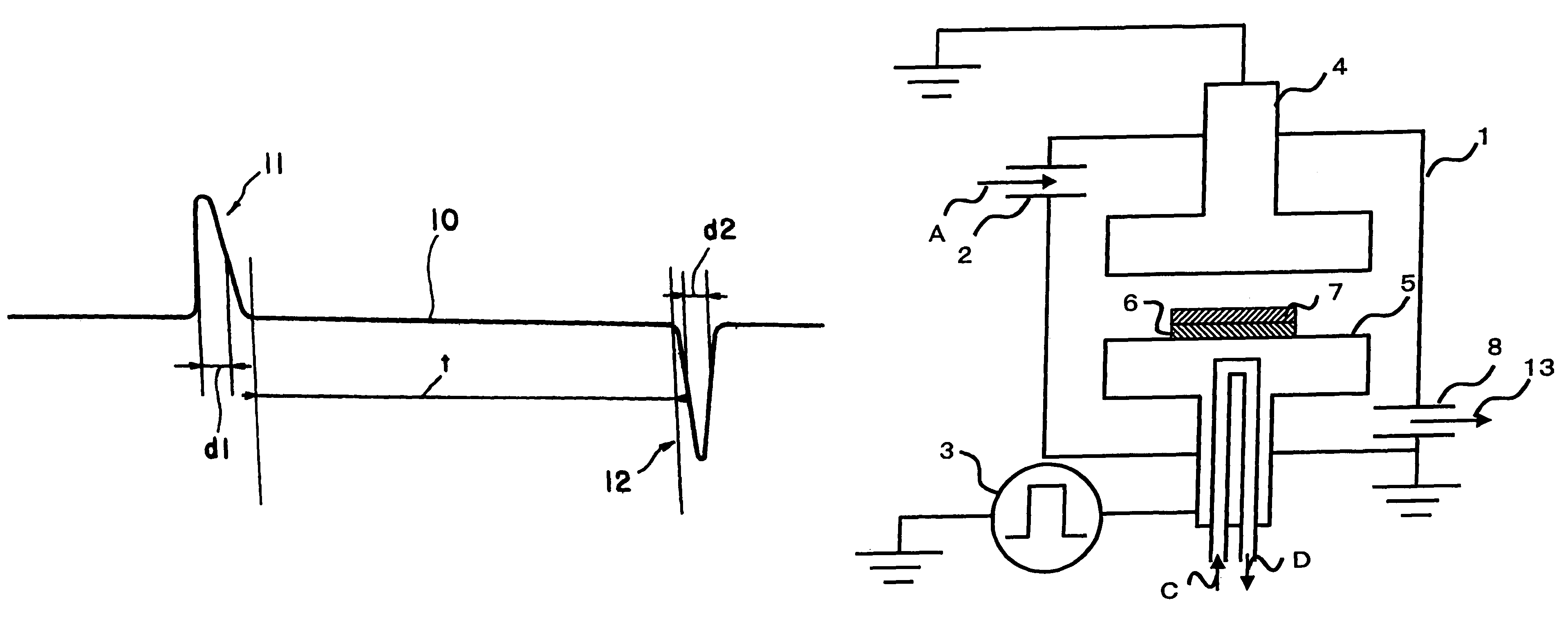
a discharge plasma and plasma technology, applied in the direction of electric variable regulation, manufacturing tools, instruments, etc., can solve the problems of difficult to generate and maintain discharge plasmas with high electron density and low electron temperature, and achieve the effect of reducing the duty ratio of pulse voltage, reducing the off-time of pulses, and reducing the electron temperature of plasmas
- Summary
- Abstract
- Description
- Claims
- Application Information
AI Technical Summary
Benefits of technology
Problems solved by technology
Method used
Image
Examples
experiment 1
(Experiment 1)
[0069]The system explained referring to FIG. 3 was used to generate glow discharge and plasma. A chamber 1 was made of stainless steel and substantially had a shape of a disk. The height of the chamber was 300 mm and the diameter φ was 300 mm. The chamber 1 was equipped with a view window 16, a Langmuir probe 17 and an electrode 5 made of stainless steel. The electrode 5 and the chamber 1 were insulated with an insulator 14. The height “D” of the probe was made 60 mm and the diameter “E” of the electrode 5 was made 100 mm. A power source using a static induction thyristor device was used as a power source.
[0070]A rotary pump and a turbo molecular pump were used to evacuate the chamber 1 until the pressure of argon gas in the chamber 1 reached 2.6 Pa. Positive pulses were periodically applied. The positive pulse had a peak value of +10.0 kV and a frequency of 1 to 10 kHz. The half value width of the positive pulse was 1000 nsec. The duty ratio of the pulse voltage was v...
experiment 2
(Experiment 2)
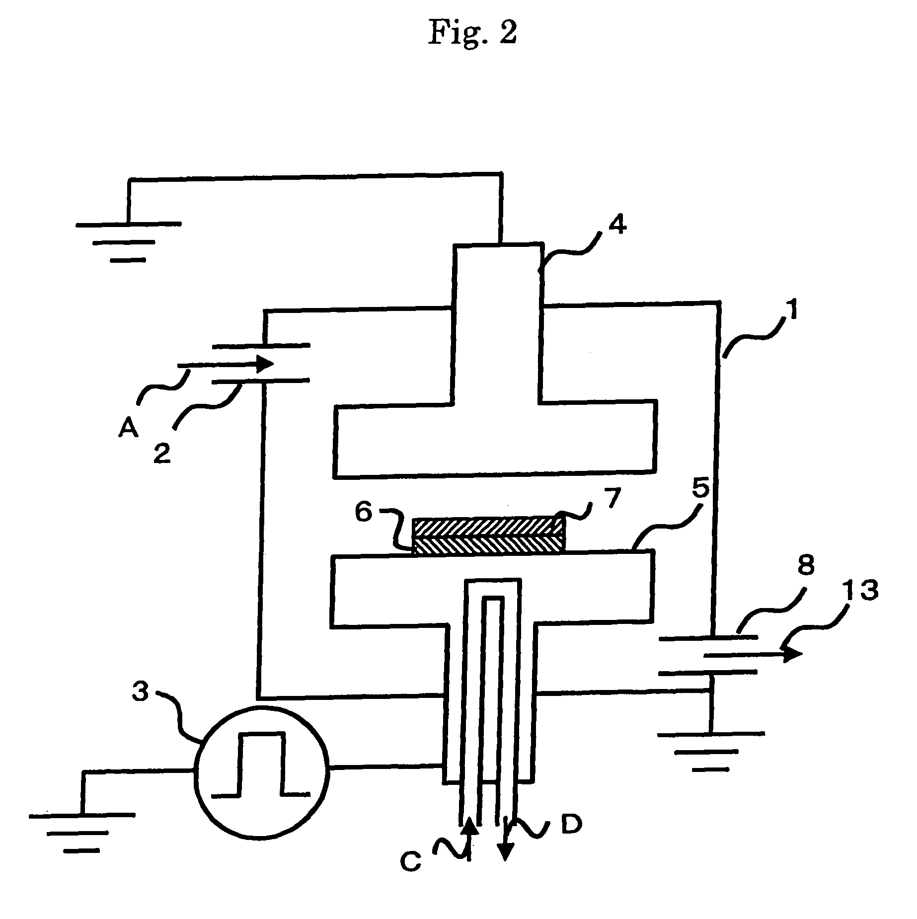
[0075]The system explained referring to FIG. 2 was used to produce a thin film of diamond-like carbon, as described above. A chamber 1 was made of stainless steel and substantially had a shape of a disk. The height of the chamber was 300 mm and the diameter φ was 300 mm. A power source using a static induction thyristor device was used as a power source.
[0076]An rotary pump and an oil diffusion pump were used to evacuate the chamber 1 until a pressure in the chamber 1 reached 1×10⁻² to 1×10⁻³ Pa. Acetylene gas was then supplied into the chamber 1 through a supply hole until the pressure in the chamber reached 2.6 Pa. Pulse voltage was then applied on the upper electrode 4 and the lower electrode 5.
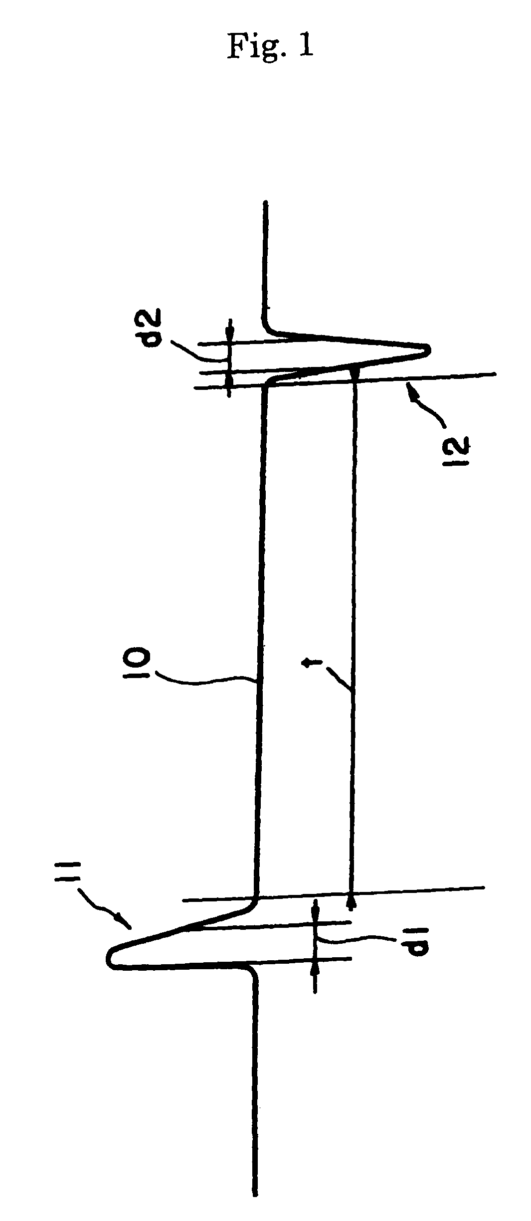
[0077]Positive pulses 11 and negative pulses 12 were periodically and alternately applied. The positive pulse 11 had a peak value of +10.0 kV and the negative pulse 12 had a peak value of −10.0 kV. The positive pulse had a frequency of 1 to 5 kHz and the distance “t” between ...
PUM
| Property | Measurement | Unit |
|---|---|---|
| electron density | aaaaa | aaaaa |
| pressure | aaaaa | aaaaa |
| off-time | aaaaa | aaaaa |
Abstract
Description
Claims
Application Information
 - R&D
- Intellectual Property
- Life Sciences
- Materials
- Tech Scout
- Unparalleled Data Quality
- Higher Quality Content
- 60% Fewer Hallucinations
Browse by: Latest US Patents, China's latest patents, Technical Efficacy Thesaurus, Application Domain, Technology Topic, Popular Technical Reports.
© 2025 PatSnap. All rights reserved.Legal|Privacy policy|Modern Slavery Act Transparency Statement|Sitemap|About US| Contact US: help@patsnap.com


