Support material for tissue engineering, for producing implants or implant materials, and an implant produced with the support material

a technology for supporting materials and tissue engineering, which is applied in the direction of skin implants, biochemistry apparatus and processes, prosthesis, etc., can solve the problems of low compressive stability of scaffolds made of textile materials, non-woven materials, fiber textiles or knitted textiles, and inhomogeneous structure of non-woven structures, etc., to achieve high fiber density

Inactive Publication Date: 2010-07-27
DRESDEN UNIVERSITY OF TECHNOLOGY
View PDF10 Cites 20 Cited by
  • Summary
  • Abstract
  • Description
  • Claims
  • Application Information

AI Technical Summary

Benefits of technology

[0012]The denser the flocking and the shorter the fibers, the less the fibers can buckle laterally under pressure, since they are prevented from doing so by the neighboring fibers.
[0013]The biocompatible scaffold material according to the invention is produced according to the process of electrostatic flocking known from textile engineering. In this connection, biocompatible fibers are attached to a biocompatible surface material almost perpendicularly. The electrostatic flocking is carried out preferably with direct current. To achieve the high fiber density according to the invention, the electrostatic field strength must be varied. Preferably, the base material on the side to be flocked will be coated with adhesive for the electrostatic flocking. The coating with adhesive is dispensable, when the base material itself has a sticky surface.

Problems solved by technology

Today, non-woven materials are often used, which however show disadvantageous inhomogenities in their structure.
The organisation of the fiber arrangement in non-woven structures is only possible to a limited extent due to the high variance of the fiber orientation.
Scaffolds made from textile materials, particularly from non-woven materials, fiber textiles or knitted textiles, show a very low compressive stability due to the predominantly horizontal arrangement of the fibers.

Method used


Image

  • Support material for tissue engineering, for producing implants or implant materials, and an implant produced with the support material
  • Support material for tissue engineering, for producing implants or implant materials, and an implant produced with the support material
  • Support material for tissue engineering, for producing implants or implant materials, and an implant produced with the support material

Examples


Embodiment Construction

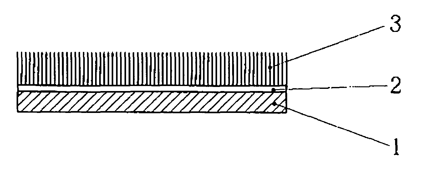
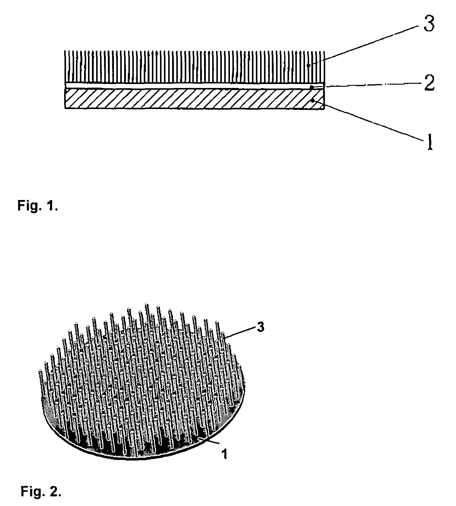
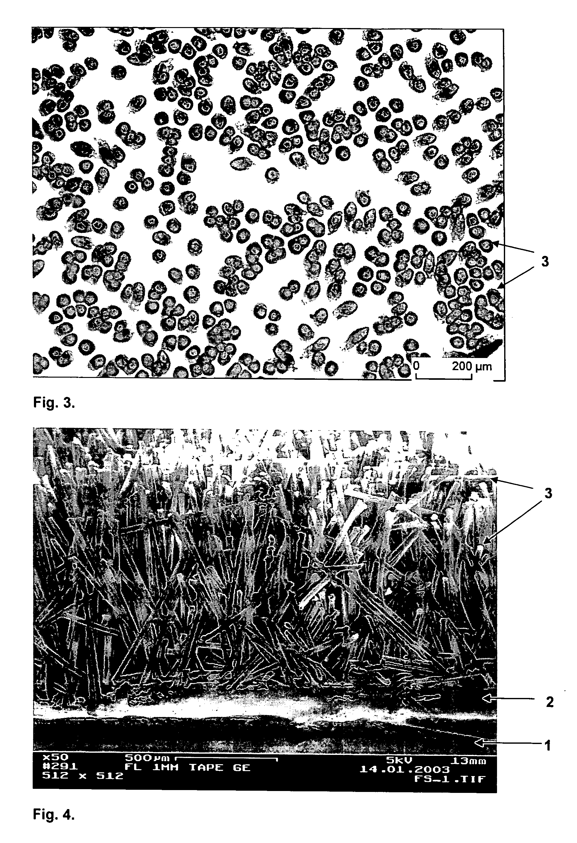
[0072]The scaffold represented in FIG. 1 consists of a flat base material 1, which is coated with an adhesive layer 2 on one side and electrostatically flocked with fibers 3 that are 1 mm long.

[0073]A mineralized hydroxyapatite-collagen-tape with a diameter of 7 cm and a mean thickness of 0.2 mm was selected as a biocompatible, resorbable base material 1. The hydroxyapatite-collagen-tape is produced from mineralized collagen (EP 0 945 146, EP 0 945 147, U.S. Pat. No. 6,384,196, U.S. Pat. No. 6,384,197, J.-H. Bradt, M. Mertig, A. Teresiak, W. Pompe: Biomimetic mineralization of collagen by combined fibril assembly and calcium phosphate formation. Chem. Mater. 1999, 11, 2694-2701), as described in R. Burth, M. Gelinsky, W. Pompe: Collagen-hydroxyapatite tapes—a new implant material, Tech. Textile 1999, 8, 20-21.

[0074]The adhesive 2 consists of Pharma-Gelatine, DGF Stoess AG, Eberbach, Germany, a biocompatible, resorbable material.

[0075]The fibers 3 have a length of 1 mm and a diameter...


PUM

PropertyMeasurementUnit
lengthaaaaaaaaaa
lengthaaaaaaaaaa
diameteraaaaaaaaaa

Abstract

A scaffold for tissue culture and cell culture and for producing implant materials, in particular bone, cartilage or skin replacements or extra-corporal organ replacements or for other applications in medicine or biotechnology is made of biocompatible materials. It has at least one base material which is electrostatically flocked with fibers on at least one side. Through the electrostatic flocking the fibers are arranged almost perpendicularly on the surface of the base material and exhibits a high fiber pull-out resistance. The scaffold provides an elastic growth lattice, which is stable against compression, for cell colonization in vitro or the ingrowth of cells in vivo. Implants or implant materials can be produced with the scaffold.

Description

BACKGROUND OF THE INVENTION[0001]The invention relates to a support material for tissue culture and cell culture (tissue engineering) for the production of implant materials, in particular bone, cartilage or skin replacements or extra-corporal organ replacements or for other applications in medicine or biotechnology. The invention further relates to an implant produced with the scaffold.[0002]It is already known to cultivate cells on support material (scaffold) and use the thereby produced tissue culture as a tissue replacement. For example, gels, fiber materials, porous ceramics or other two- or three-dimensional structures are used as scaffolds. The treatment of different tissues, for example, cartilage, that are defective through injury, wear or sickness by means of grown tissue cultures is already known. For this purpose, endogenous cells are introduced, for example, into three-dimensional scaffolds, proliferated in vitro, and the material so produced is implanted in the body. T...

Claims


Application Information

Patent Timeline
Patent Type & Authority Patents(United States)
IPC IPC(8): A61F2/02A61L27/18A61L27/38C12N5/00C12N5/02
CPCA61F2/30756A61L27/18A61L27/3633A61L27/38A61L27/3847A61L27/3852C12N5/0068C08L67/04A61F2/105A61F2002/30062A61F2002/30225A61F2002/30448A61F2002/30602A61F2002/30762A61F2002/30766A61F2002/30892A61F2002/30971A61F2002/4648A61F2210/0004A61F2220/005A61F2230/0069A61F2310/00365A61F2310/00383C12N2533/40C12N2533/50C12N2533/54C12N2533/70C12N2533/72A61L2430/06B33Y80/00
Inventor OFFERMANN, PETERWORCH, HARTMUTPOMPE, WOLFGANGGELINSKY, MICHAELSCHMACK, GERHILTHOFFMANN, GERALDKOCKRITZ, UWE
Owner DRESDEN UNIVERSITY OF TECHNOLOGY
Why Eureka
Try Eureka