UV light irradiating apparatus with liquid filter

a technology of irradiating apparatus and liquid filter, which is applied in the direction of optical radiation measurement, instruments, therapy, etc., can solve the problems of reducing the effective irradiation efficiency, affecting throughput, and reducing the quantity of effective irradiation light reaching the irradiation target, so as to improve the mechanical strength of the low-k film, reduce the effect of effective irradiation light and increase the energy consumption

Active Publication Date: 2010-07-27
ASM JAPAN
View PDF21 Cites 365 Cited by
  • Summary
  • Abstract
  • Description
  • Claims
  • Application Information

AI Technical Summary

Benefits of technology

[0005]UV irradiation has the effect of enhancing the mechanical strength of a low-k film by breaking the —CH3 bond or —Si—O bond in film and then re-bonding the broken components to build an O—Si—O network. This effect is stronger with UV light with short wavelengths because such light generates higher energy. Various types of lamps can be used for UV curing, such as excimer lamps and mercury lamps. Among these, mercury lamps produce light of various wavelengths and generate a lot of heat as a result, and therefore these lamps require cooling. Normally mercury lamps are cooled by a blower supplying cooling air. Since the oxygen in cooling air absorbs UV light with a wavelength of 250 nm or shorter and converts it to ozone, however, the quantity of effective UV light reaching the irradiation target will decrease. As a result, the curing efficiency will drop and the throughput will also be affected. Furthermore, generated ozone is harmful and thus the exhaust gas must be treated with a scrubber method, etc. If the input power to the lamp is increased in an attempt to increase the quantity of effective UV light with a wavelength of 250 nm or shorter, more heat will generate and the temperature of the curing target, i.e., the substrate on which a low-k film has been deposited, will also increase. Accordingly, there is a limit to how much the input power can be increased.
[0006]To solve at least one of the aforementioned problems, an embodiment of the present invention changes the lamp cooling method from air-cooling to water-cooling. Since this eliminates the need for use of atmospheric air for cooling, the required UV light with a wavelength of 250 nm or shorter will not be absorbed by the oxygen in cooling air, which in turn enables effective UV processing. UV light with a wavelength of 250 nm or shorter is effective in curing low-k films. In particular, UV light with a wavelength in a range of 200 to 250 nm is very effective. A lot of air is needed to cool mercury lamps, but as noted above, effective light with a wavelength of 250 nm or shorter is absorbed by the oxygen in air and converted to harmful ozone. Use of nitrogen is not practical in view of the large quantity of nitrogen required. These concerns will no longer be necessary if the aforementioned embodiment is used. In another embodiment, the atmosphere in the lamp unit is replaced with N2 to prevent UV light with a wavelength of 250 nm or shorter from being absorbed by the oxygen in cooling air. Another problem, as mentioned before, is that if the intensity of UV light with a wavelength of 250 nm or shorter is raised to improve the curing efficiency, the greater heat generated from the lamp will increase the temperature of the irradiated substrate. Consequently, the intensity of UV light can only be increased to a certain level. In an embodiment, a water-cooled lamp is used to increase the intensity of UV light without causing problems associated with heat.

Problems solved by technology

Among these, mercury lamps produce light of various wavelengths and generate a lot of heat as a result, and therefore these lamps require cooling.
Since the oxygen in cooling air absorbs UV light with a wavelength of 250 nm or shorter and converts it to ozone, however, the quantity of effective UV light reaching the irradiation target will decrease.
As a result, the curing efficiency will drop and the throughput will also be affected.
Furthermore, generated ozone is harmful and thus the exhaust gas must be treated with a scrubber method, etc.
Accordingly, there is a limit to how much the input power can be increased.
A lot of air is needed to cool mercury lamps, but as noted above, effective light with a wavelength of 250 nm or shorter is absorbed by the oxygen in air and converted to harmful ozone.
Use of nitrogen is not practical in view of the large quantity of nitrogen required.
Another problem, as mentioned before, is that if the intensity of UV light with a wavelength of 250 nm or shorter is raised to improve the curing efficiency, the greater heat generated from the lamp will increase the temperature of the irradiated substrate.

Method used


Image

  • UV light irradiating apparatus with liquid filter
  • UV light irradiating apparatus with liquid filter
  • UV light irradiating apparatus with liquid filter

Examples


Embodiment Construction

[0017]The present invention will be explained with reference to preferred embodiments. However, the preferred embodiments are not intended to limit the present invention.

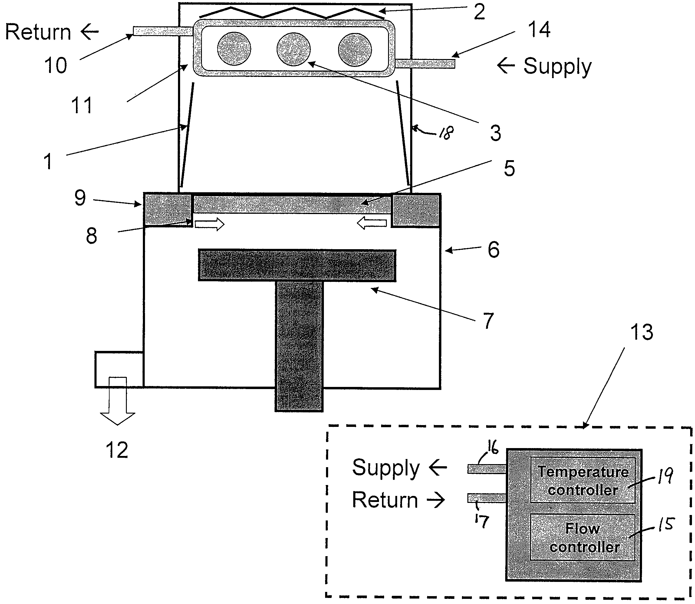
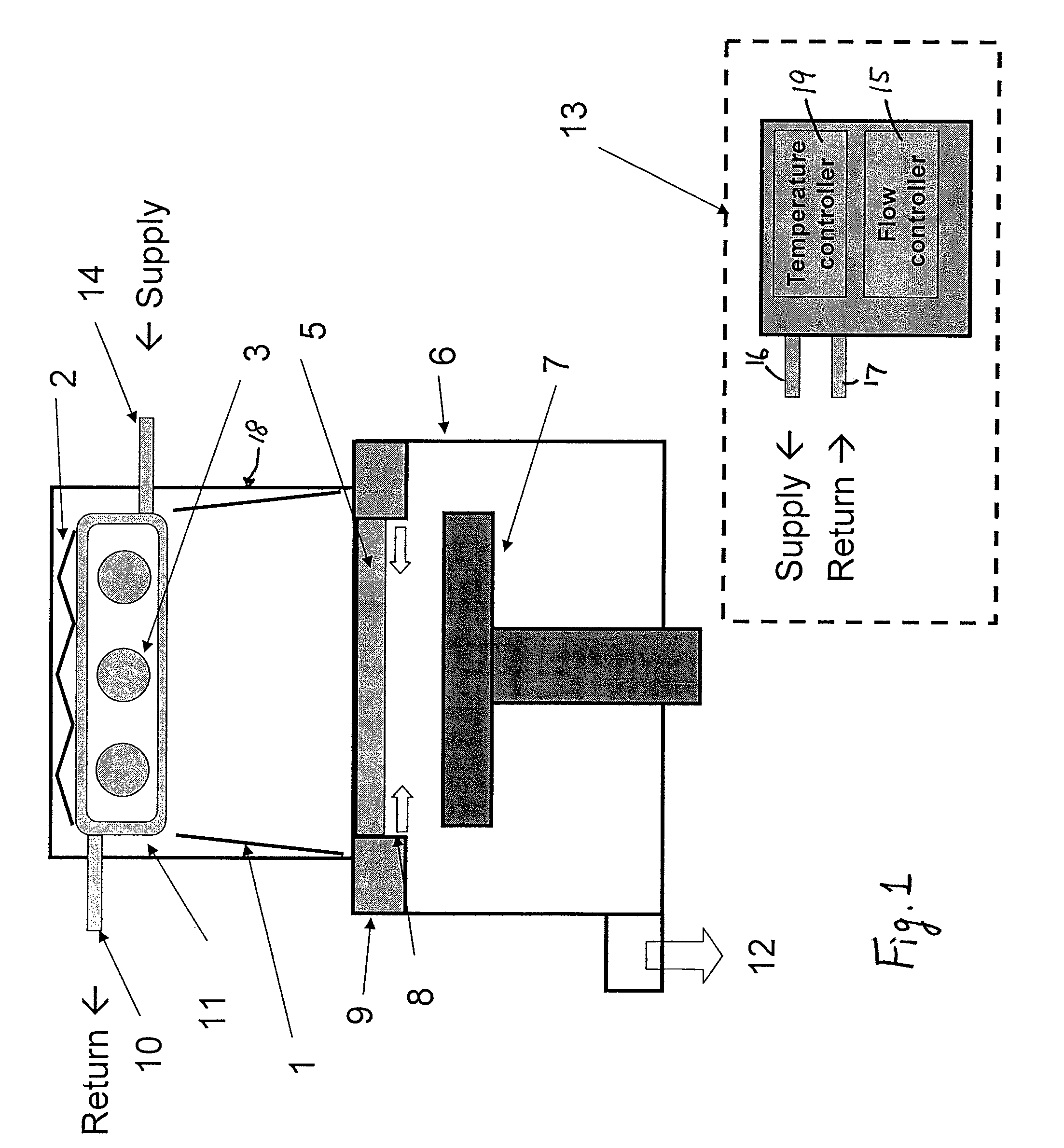
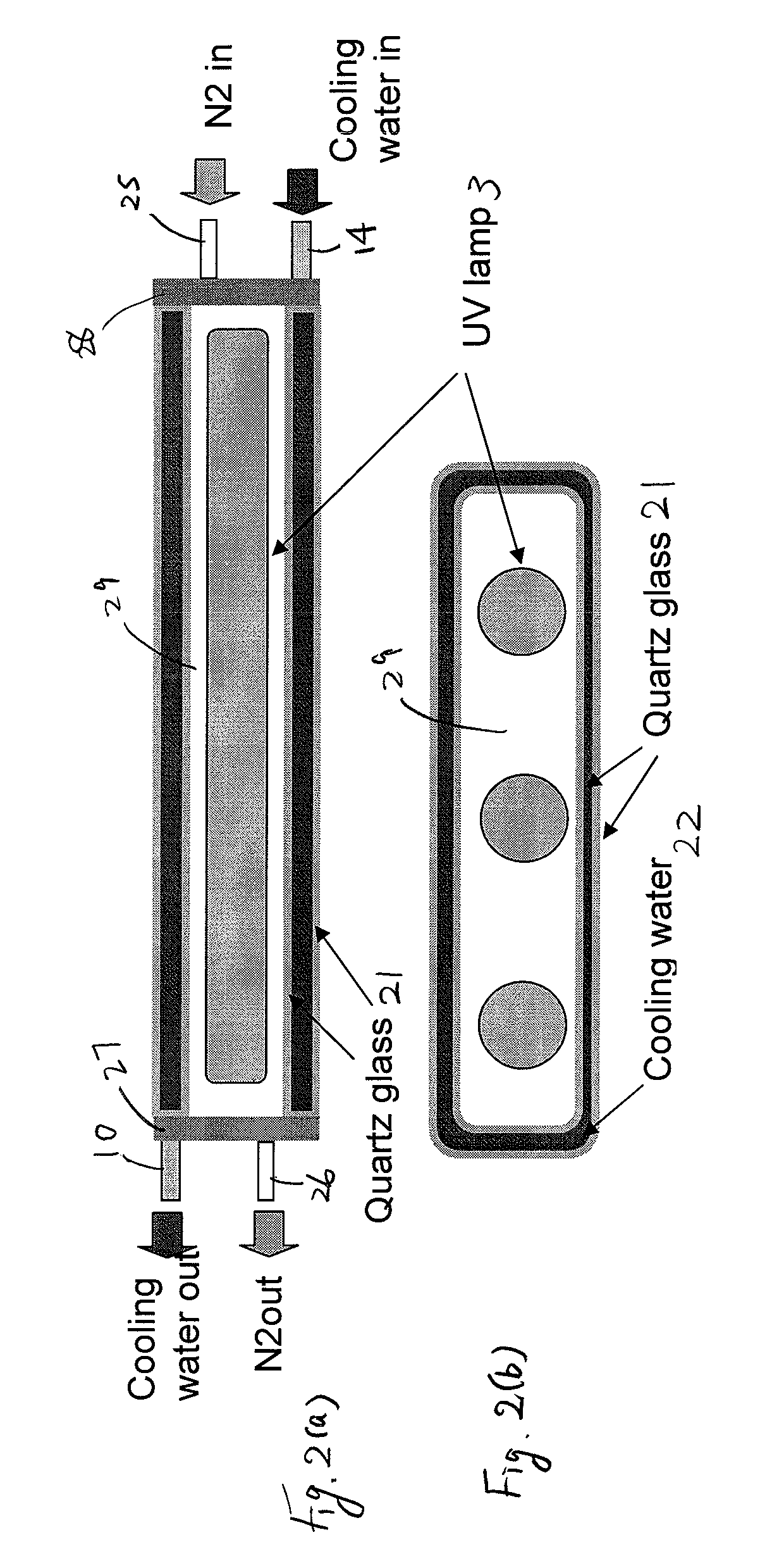
[0018]In an embodiment, the present invention provides a UV light irradiating apparatus for irradiating a semiconductor substrate with UV light, comprising: (i) a reactor in which a substrate-supporting table is provided, said reactor being provided with a light transmission window; (ii) a UV light irradiation unit connected to the reactor for irradiating a semiconductor substrate placed on the substrate-supporting table with UV light through the light transmission window, said UV light irradiation unit including at least one UV lamp; and (iii) a liquid layer forming channel disposed between the light transmission window and the UV lamp for forming a liquid layer through which the UV light is transmitted, said liquid layer being formed by a liquid flowing through the liquid layer forming channel.

[0019]The above embo...


PUM


Abstract

A UV light irradiating apparatus for irradiating a semiconductor substrate with UV light includes: a reactor in which a substrate-supporting table is provided; a UV light irradiation unit connected to the reactor for irradiating a semiconductor substrate placed on the substrate-supporting table with UV light through a light transmission window; and a liquid layer forming channel disposed between the light transmission window and at least one UV lamp for forming a liquid layer through which the UV light is transmitted. The liquid layer is formed by a liquid flowing through the liquid layer forming channel.

Description

BACKGROUND OF THE INVENTION[0001]1. Field of the Invention[0002]The present invention generally relates to a UV light irradiating apparatus or a method for irradiating a semiconductor substrate.[0003]2. Description of the Related Art[0004]Traditionally, UV processing apparatuses have been used in the reforming of various processing targets using ultraviolet light or in the production of substances through processes that utilize photochemical reactions. The trend of increasingly integrated devices in recent years has created needs for refined wiring designs and multi-layer wiring structures, which has made it vital to reduce inter-layer volumes to increase the processing speeds of devices while reducing their power consumptions. Low-k (low-dielectric-constant film) materials are used to reduce inter-layer volumes. However, reducing the dielectric constant of a material also reduces its mechanical strength (elastic modulus, or EM), which makes it difficult for the low-k material to wi...

Claims


Application Information

Patent Timeline
Patent Type & Authority Patents(United States)
IPC IPC(8): G21K5/02
CPCH01L21/67115H01L21/6715G03F7/20
Inventor MATSUSHITA, KIYOHIROKAGAMI, KENICHI
Owner ASM JAPAN
Why Eureka
Try Eureka