Aluminum alloy tube and fin assembly for heat exchangers having improved corrosion resistance after brazing

a technology of aluminum alloy and heat exchanger, which is applied in the direction of coatings, transportation and packaging, lighting and heating apparatus, etc., can solve the problems of affecting affecting the corrosion resistance of the aluminum alloy, and the failure of the alloy much faster than the perforation and failure of the fillet, so as to improve the thermal performance of the assembly, slow and uniform corrosion of the exposed fin surface, and good self-anti-corrosion results

Active Publication Date: 2010-08-24
ALCAN INT LTD
View PDF20 Cites 13 Cited by
  • Summary
  • Abstract
  • Description
  • Claims
  • Application Information

AI Technical Summary

Benefits of technology

[0017]It appears that the above unique combination of alloying elements for the tubes gives unexpectedly good self anti-corrosion results for the tubes without the need for any coating of zinc. Also by keeping the manganese content of the tube alloy within 0.8% by weight of that of the fin or greater than or equal to the manganese content in the fin, the fin remains sacrificial, thus protecting the tube and the galvanic corrosion current remains relatively low so that the fin is not corroded so rapidly in service that the thermal performance of the assembly is compromised.
[0018]The above combination of aluminum alloy fins and extruded tubes when assembled and furnace brazed exhibit a very slow and uniform corrosion of exposed fin surfaces, rather than localized pitting of the tube. The invention is particularly useful when the tubes are microport tubes and the assembly has been furnace brazed in an inert atmosphere.

Problems solved by technology

A difficulty with the use of aluminum alloy products in corrosive environments, such as automotive heat exchanger tubing, is pitting corrosion.
Once small pits start to form, corrosion actively concentrates in the region of the pits, so that perforation and failure of the alloy occurs much more rapidly than it would if the corrosion were more general.
A problem with thermally spraying with zinc before brazing is therefore that the braze fillets become zinc enriched and tend to be the first parts of the units to corrode.
As a result, the fins become detached from the tubes, reducing the thermal efficiency of the heat exchanger.
In addition to these physical effects, any enrichment of the fillet region with Zn has the effect of reducing the thermal conductivity of the prime heat transfer interface between the tube / fin.
However, this has a negative impact on the thermal conductivity of the fin and on the ultimate recyclability of the unit.
Furthermore, if the fin material is too electronegative it can corrode too fast and thereby compromises the thermal performance of the entire heat exchanger.
Little attempt has been made to optimize the tube-fin combination in heat exchangers based on extruded tubes through the use of appropriate alloys alone, the use of zinc cladding being widely used instead.
It has a titanium content of 0.03 to 0.30%, but this level of titanium raises the pressures required for extrusion, which will ultimately lower productivity.

Method used


Image

  • Aluminum alloy tube and fin assembly for heat exchangers having improved corrosion resistance after brazing
  • Aluminum alloy tube and fin assembly for heat exchangers having improved corrosion resistance after brazing
  • Aluminum alloy tube and fin assembly for heat exchangers having improved corrosion resistance after brazing

Examples


example 1

[0034]Tests were conducted using the alloys listed in Table 1 below:

[0035]

TABLE 1AlloyCuFeMgMnNiSiTiZnA0.090.220.0580.0170.004B0.0140.070.230.070.0080.17C0.0150.510.0210.330.0010.320.0140.007D0.0010.080.980.0020.0640.0140.18E0.0150.091.000.070.0070.18F0.080.980.0010.0710.0080.005G0.0060.110.0010.420.0010.0780.0230.027H0.0060.100.0020.630.0010.0790.0210.029I0.0010.090.610.0020.080.0160.002J0.00350.110.620.0020.090.0160.002K0.080.591.050.230.010.01

[0036]These alloys were cast into 152 mm diameter billets. Alloy C was a commercial 3102 alloy and Alloy K a commercial 3003 alloy. The billets were further machined down to 97 mm in diameter and homogenized between 580 and 620° C. They were then extruded into tubes. Samples of the tubing were subjected to a simulated brazing process and then subjected to a SWAAT test using ASTM standard G85 Annex 3 and galvanic corrosion currents were measured against a standard finstock material manufactured from AA3003 alloy containing 1.5% by weight adde...

example 2

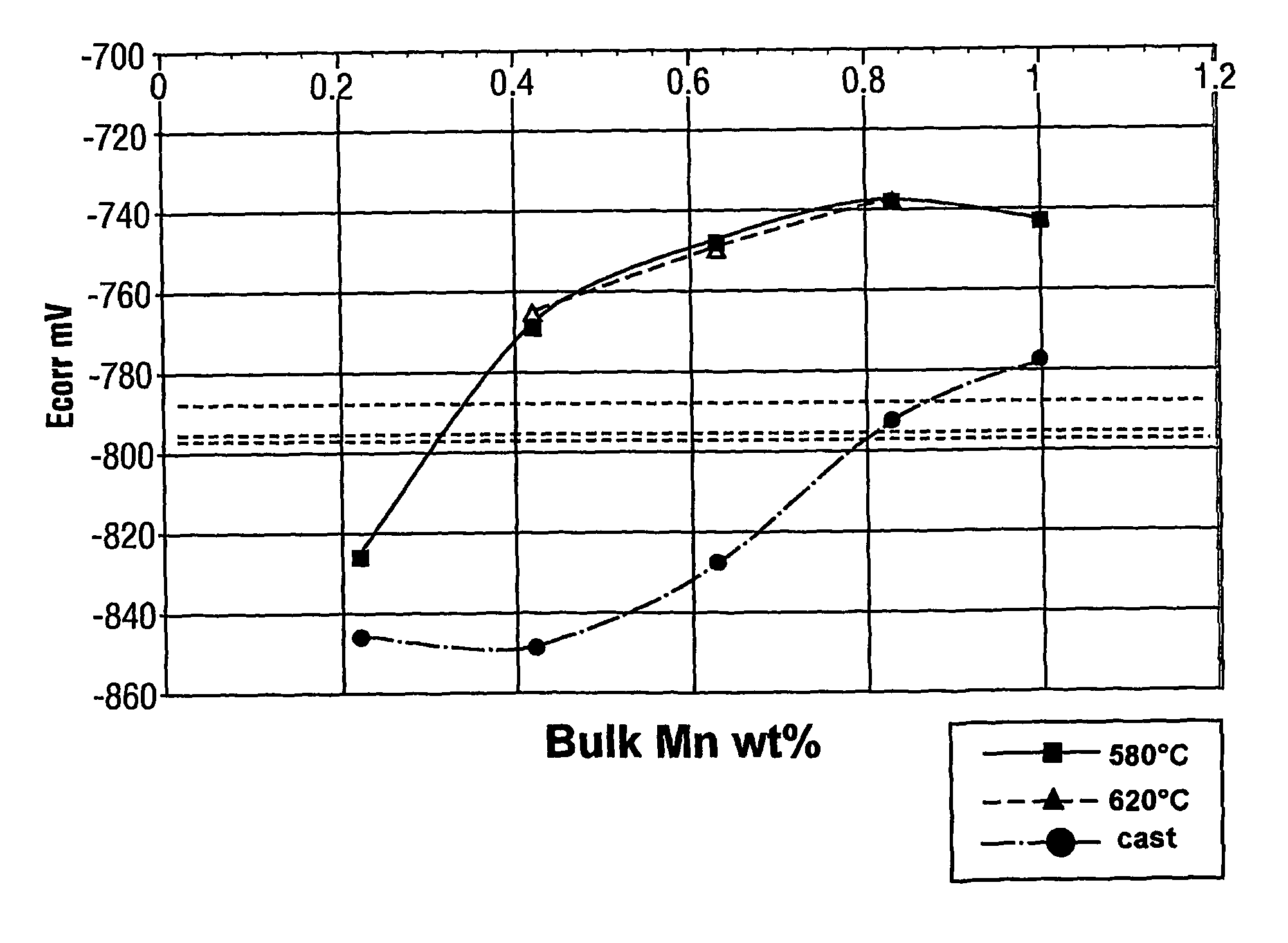
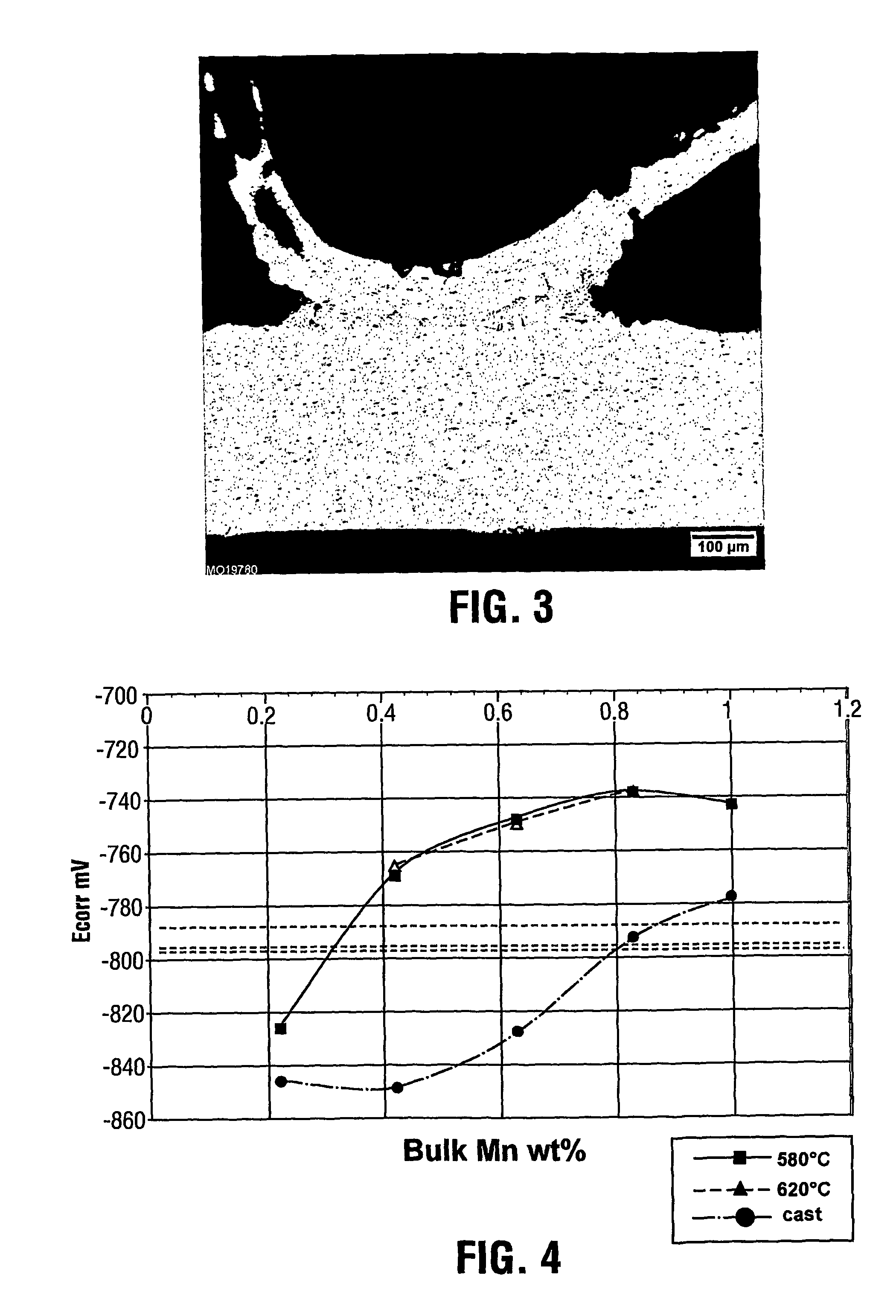
[0045]In order to show the effect of changes in fin Mn composition, the corrosion potential of the various tube alloys of Example 1 were compared to the corrosion potential of various fin alloys. A necessary condition for the fin to be sacrificial with respect to the tube is that the tube corrosion potential be clearly less negative than the fin corrosion potential. The corrosion potential of the tube alloys of Example 1 were determined and plotted on a graph in FIG. 4 showing the variation with manganese content. Curves are shown for the tube alloys in the as-cast condition as well as following homogenization at 580 or 620° C.

Various fin alloys (identified as samples 1 to 3) based on the commercial AA3003 with 1.5% Zn composition, but having different Mn compositions within the preferred Mn range of the present invention, were prepared by book mould casting, processed to finstock gauge by hot and cold rolling. They were then subjected to a simulated braze cycle and the corrosion po...


PUM

PropertyMeasurementUnit
weight percentaaaaaaaaaa

Abstract

The present invention provides extruded tubes for heat exchangers having improved corrosion resistance when used alone and when part of a brazed heat exchanger assembly with compatible finstock. The tubes are formed from a first aluminum alloy containing 0.4 to 1.1% by weight manganese, up to 0.01% by weight copper, up to 0.05% by weight zinc, up to 0.2% by weight iron, up to 0.2% by weight silicon, up to 0.01% by weight nickel, up to 0.05% by weight titanium and the balance aluminum and incidental impurities. The fins are formed from a second aluminum alloy containing 0.9 to 1.5% by weight manganese or an alloy of the AA3003 type, this second aluminum alloy further containing at least 0.5% by weight zinc.

Description

CROSS-REFERENCE TO RELATED APPLICATIONS[0001]This application is a National Stage entry of PCT / CA03 / 02002, filed Dec. 22, 2003, which claims priority from U.S. Provisional Application No. 60 / 436,022, filed Dec. 23, 2002.TECHNICAL FIELD[0002]This invention relates to extruded aluminum alloy products of improved corrosion resistance. It particularly relates to extruded tubes for heat exchangers having improved corrosion resistance after brazing when paired with a compatible finstock.BACKGROUND ART[0003]Commercially produced aluminum microport tubing for use in brazed applications is generally produced in the following manner. The extrusion ingot is cast and optionally homogenized by heating the metal to an elevated temperature and then cooling in a controlled manner. The ingot is then reheated and extruded into microport tubing. This is generally thermally sprayed with zinc before quenching, drying and coiling. The coils are then unwound, straightened and cut to length. The tubes obta...

Claims


Application Information

Patent Timeline
Patent Type & Authority Patents(United States)
IPC IPC(8): F28F19/02F28F21/08B32B15/20C22C21/00
CPCC22C21/00C22C21/10F28F21/084C22F1/04Y10S165/905Y10T428/12764
Inventor PARSON, NICHOLAS CHARLESGRAY, ALANMAROIS, PIERRE HENRIRAMANAN, THIAGARAJAN
Owner ALCAN INT LTD
Why Eureka
Try Eureka