Soundproofing assembly, use for soundproofing enclosed spaces, and method for making same

a technology of soundproofing and assembly, which is applied in the direction of sound producing devices, building components, lamination, etc., can solve the problems of not being able to provide practically no insulation, the system is not very effective in the medium frequency range, and the weight of the layer 14/b> forming the heavy mass must be substantial, so as to achieve greater soundproofing and high tortuosity

Active Publication Date: 2010-09-07
FAURECIA AUTOMOTIVE IND
View PDF8 Cites 11 Cited by
  • Summary
  • Abstract
  • Description
  • Claims
  • Application Information

AI Technical Summary

Benefits of technology

[0034]In the case where the sources of noise necessitate greater soundproofing in the low frequency range between 200 and 400 Hz it is possible to use for the layer of the spring type a viscoelastic foam (for example with partially closed cells) which has the advantage that it gives structural damping in the range of low frequencies between 200 and 400 Hz and has a loss factor of the order of 0.2 to 0.45, whilst that of the layer with high tortuosity is of the order of 0.1 to 0.2. The reduction in the insulation gradient, that is to say the losses through transmission, of this viscoelastic layer is compensated for by the good insulation gradient of the layer with high tortuosity.
[0035]It is advantageous if the soundproofing assembly has a thickness greater than 20 Mm.

Problems solved by technology

The problem posed by the system represented in FIG. 1 is that, due to its low absorption, the layer 14 forming the heavy mass must have a substantial weight.
Furthermore, such a system is not very effective in the medium frequency range.
The advantage thereof is that it is light, but the drawback is that it provides practically no insulation: therefore it is not appropriate when such insulation is necessary, for example, for the apron of an automobile.
The effectiveness of the system of FIG. 3 is offset by its relatively high cost.
In fact, manufacture thereof necessitates a method comprising two successive steps carried out in separate installations, which are expensive.

Method used


Image

  • Soundproofing assembly, use for soundproofing enclosed spaces, and method for making same
  • Soundproofing assembly, use for soundproofing enclosed spaces, and method for making same
  • Soundproofing assembly, use for soundproofing enclosed spaces, and method for making same

Examples


Embodiment Construction

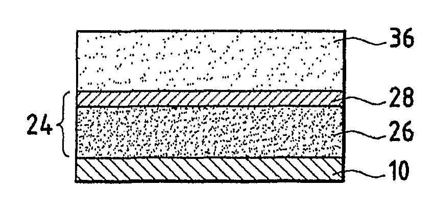
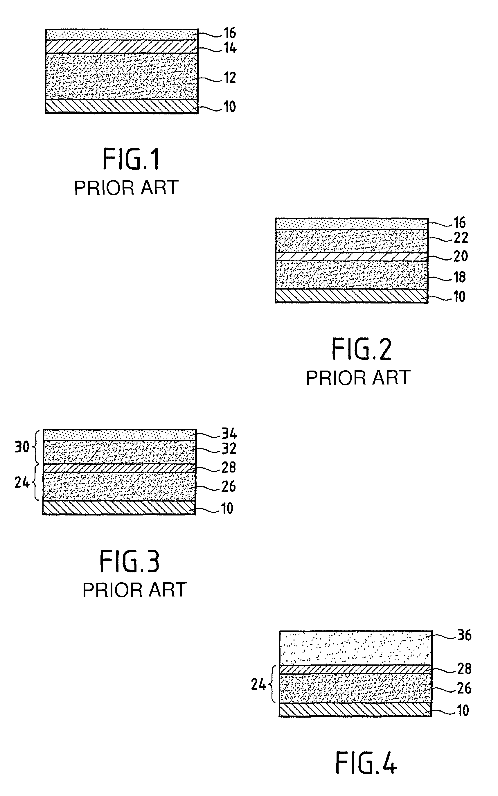
[0045]In FIG. 4 the reference 10 designates, as in the other drawings, a panel intended to support the soundproofing assembly according to the invention, for example a apron which separates an engine compartment from a passenger compartment of an automobile. This comprises first of all a second group 24 of layers comprising, as in the system of FIG. 3, a first layer 26 forming a spring and a second layer 28 forming a heavy mass. The first layer 26 forming a spring is a flexible open-cell foam, for example made from thermoplastic material, having good absorption and mechanical decoupling properties. The material of the layer 28, which is impermeable, contains dense materials such as bitumen waste, chalk, barium sulphate, bound by a thermoplastic material, for example a polyolefin such as polyethylene. Other examples of a binder are a vinyl acetate / ethylene copolymer or an ethylene-propylene-diene monomer terpolymer. This assembly may be analogous to that shown in FIG. 3. This second ...


PUM

PropertyMeasurementUnit
thicknessaaaaaaaaaa
densityaaaaaaaaaa
frequencyaaaaaaaaaa

Abstract

A soundproofing assembly includes stacked layers in the form of a first set of layers (36) having good resistance to the passage of air, and a second set of layers (24) with mass-spring function including a layer (28) having a heavy viscoelastic mass and a spring type layer (26); the first set of layers includes a layer (36) of a foam with open cells of high porosity, high tortuosity and good resistance to the passage of air, the layer (36) having, owing to its high tortuosity, excellent sonic absorption properties at medium and high frequencies. The invention is useful for soundproofing motor car passenger compartments.

Description

BACKGROUND OF THE INVENTION[0001]The present invention relates to a soundproofing assembly principally intended for soundproofing of substantially enclosed spaces, such as the passenger compartment of an automobile, application of a foam of plastics material with high tortuosity to such soundproofing, and a method of manufacture of such a soundproofing assembly.[0002]The invention relates to acoustic problems which arise in a substantially enclosed space, such as the passenger compartment of an automobile, in the vicinity of sources of noise such as an engine, the contact of tyres on a road, etc.[0003]Before the description of the prior art it is appropriate to define some terms which are useful for understanding the invention.[0004]In general, in the low frequency range, sound waves undergo a “damping” by materials in the form of single or double sheets (sandwich) or by an effect of porosity and resilience of a mass-spring system, especially using viscoelastic foam.[0005]A soundpro...

Claims


Application Information

Patent Timeline
Patent Type & Authority Patents(United States)
IPC IPC(8): E04B1/84B29D99/00
CPCG10K11/168Y10T156/1031
Inventor DUVAL, ARNAUDMARCEL, VALERIERONDEAU, JEAN-FRANCOISCHARBONNIER, PATRICE
Owner FAURECIA AUTOMOTIVE IND
Why Eureka
Try Eureka