

Neutral metallic dendrimer complexes
a technology of dendrimer complexes and metallic dendrimer, which is applied in the field of neutral metallic dendrimer complexes, can solve the problems of oled device stability being affected, generation not always giving adequate control over intermolecular interactions,
- Summary
- Abstract
- Description
- Claims
- Application Information
AI Technical Summary
Benefits of technology
Problems solved by technology
Method used
Image

Examples
example 1
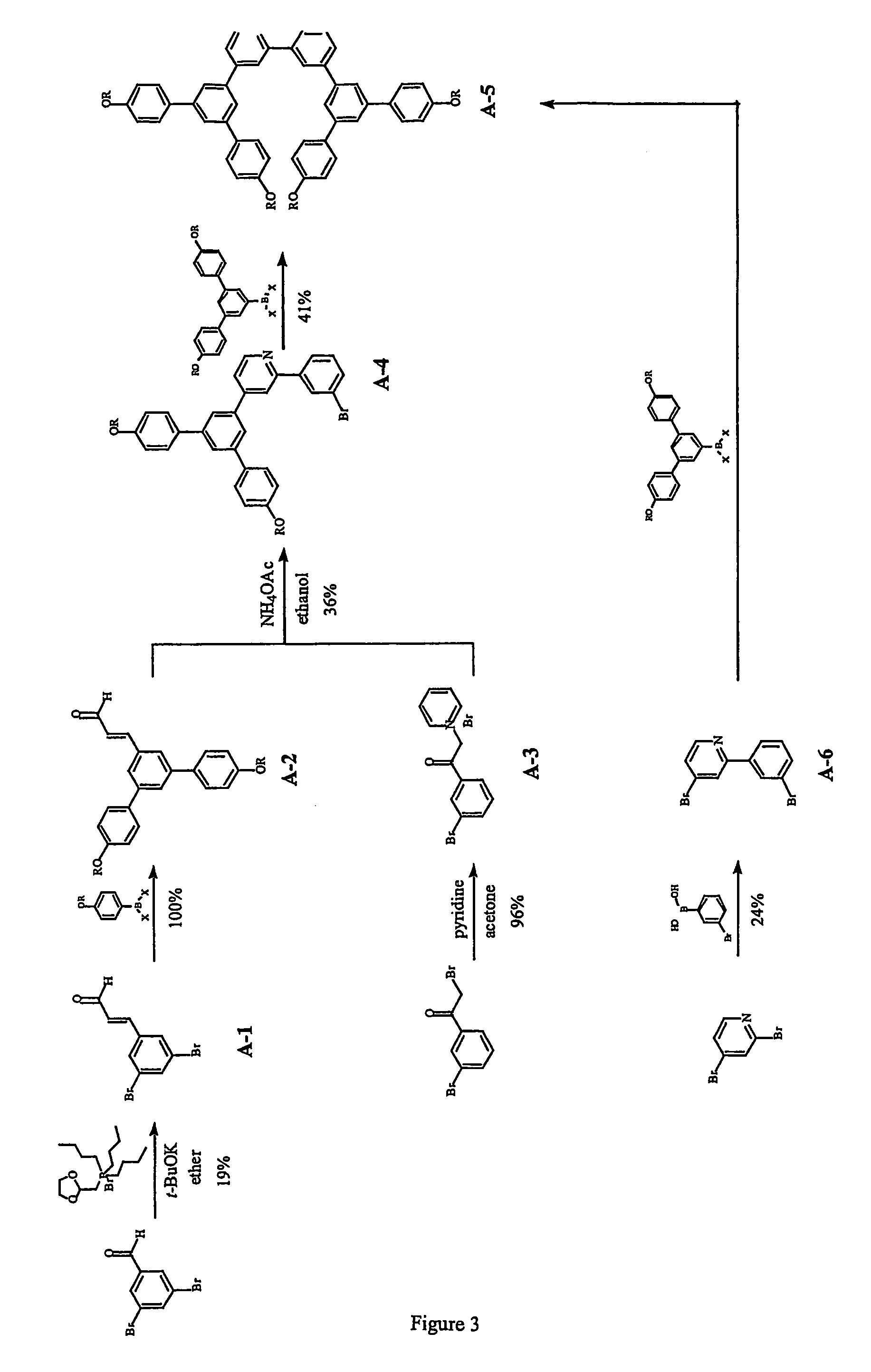
A-1
3-(3′,5′-dibromophenyl)-2-propenal
[0060]3,5-dibromobenzaldehyde (16.1 g, 61.0 mmol) was added to a cold (ice-water bath) solution of tert-butoxide (13.0 g, 116 mmol), (1,3-dioxolan-2-ylmethyl)tri-n-butylphosphine bromide salt (4.5 M, 32 cm3, 144 mmol) in 400 cm3 of ether under argon. The mixture was stirred at 0-2° C. for 2 h. 1.0 M HCl(aq) (300 cm3) was added to the mixture. The reaction was gradually warmed to room temperature and stirred at room temperature for 21 h. The two layers were separated. The aqueous layer was extracted with ether (3×200 cm3). The organic layer and the ether extracts were combined, washed with brine (1×300 cm3) and dried over anhydrous magnesium sulfate. The solvents were completely removed to leave a yellow solid. The solid was purified by column chromatography of silica gel using ethyl acetate-light petroleum (40-60° C.) as eluent to give 3.36 g (19%) of A-1 as a colourless solid; δH (200 MHz; CDCl3) 6.68 (1 H, dd, J 7.4 & 16 Hz, vinylH), 7.33 (1 H,...
example 2
A-2
3-{3′,5′-Di[4″-(2′″-ethylhexyloxy)phenyl]phenyl}-2-propenal
[0061]A mixture of the boronic compound G0-BX2 prepared in accordance with Example 4 of PCT / GB02 / 00739 (647 mg, 2.59 mmol), 3-(3′,5′-dibromophenyl)-2-propenal A-1 (326 mg, 1.24 mmol), tetrakis(triphenylphosphine) palladium (0) (91 mg, 0.079 mmol), 2 M Na2CO3(aq) (1.0 cm3), EtOH (1.0 cm3) and toluene (3.5 cm3) was degassed and then heated at reflux (with bath temperature of 106° C.) under argon for 18 h. The mixture was allowed to cool to ambient temperature and then diluted with water (5 cm3) and ether (6 cm3). The two phases were separated. The aqueous layer was extracted with ether (3×5 cm3). The organic layer and the ether extracts were combined, washed with brine (1×10 cm3) and dried over anhydrous magnesium sulfate. The solvents were completely removed. The residue was purified by column chromatography over silica gel using DCM-light petroleum (0:1 to 1:30 and 1:10) as eluent to give 607 mg (100%) of A-2 as a light y...
example 3
A-3
[0062]Pyridine (6 cm3) was added to a mixture of 3-bromophenylacylbromide (956 mg, 3.44 mmol) and 44 cm3 of acetone. The reaction was stirred at room temperature for 2 h and the solvent was removed under reduced pressure. The resulting precipitate was washed with ether (4×10 cm3) and dried under reduced pressure to leave 1.18 g (96%) of A-3 as a light pink / cream solid.
PUM
| Property | Measurement | Unit |
|---|---|---|
| thickness | aaaaa | aaaaa |
| thickness | aaaaa | aaaaa |
| thickness | aaaaa | aaaaa |
Abstract
Description
Claims
Application Information