
Liquid hydrocarbon fuel from methane assisted by spontaneously generated voltage

a technology of liquid hydrocarbon fuel and methane, which is applied in the direction of gaseous fuel, fuel, chemistry apparatus and processes, etc., can solve the problem that the rate at which the product fuel is produced far exceeds any rate of depletion of the liquid reaction medium

Active Publication Date: 2010-10-05
GUNNERMAN RUDOLF W +1
View PDF2 Cites 17 Cited by
  • Summary
  • Abstract
  • Description
  • Claims
  • Application Information

AI Technical Summary

Benefits of technology

The process results in a liquid fuel with significantly improved fuel efficiency, exceeding conventional fuels by 30% or more miles per gallon, and a production rate that outpaces the depletion of the reaction medium, while minimizing emissions and offering a versatile and efficient energy output.

Problems solved by technology

Furthermore, the rate at which the product fuel is produced far exceeds any rate of depletion of the liquid reaction medium.

Method used


Image

  • Liquid hydrocarbon fuel from methane assisted by spontaneously generated voltage
  • Liquid hydrocarbon fuel from methane assisted by spontaneously generated voltage
  • Liquid hydrocarbon fuel from methane assisted by spontaneously generated voltage

Examples


example 1

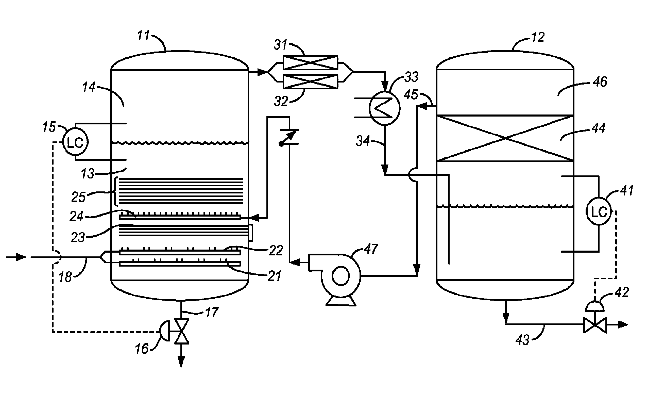
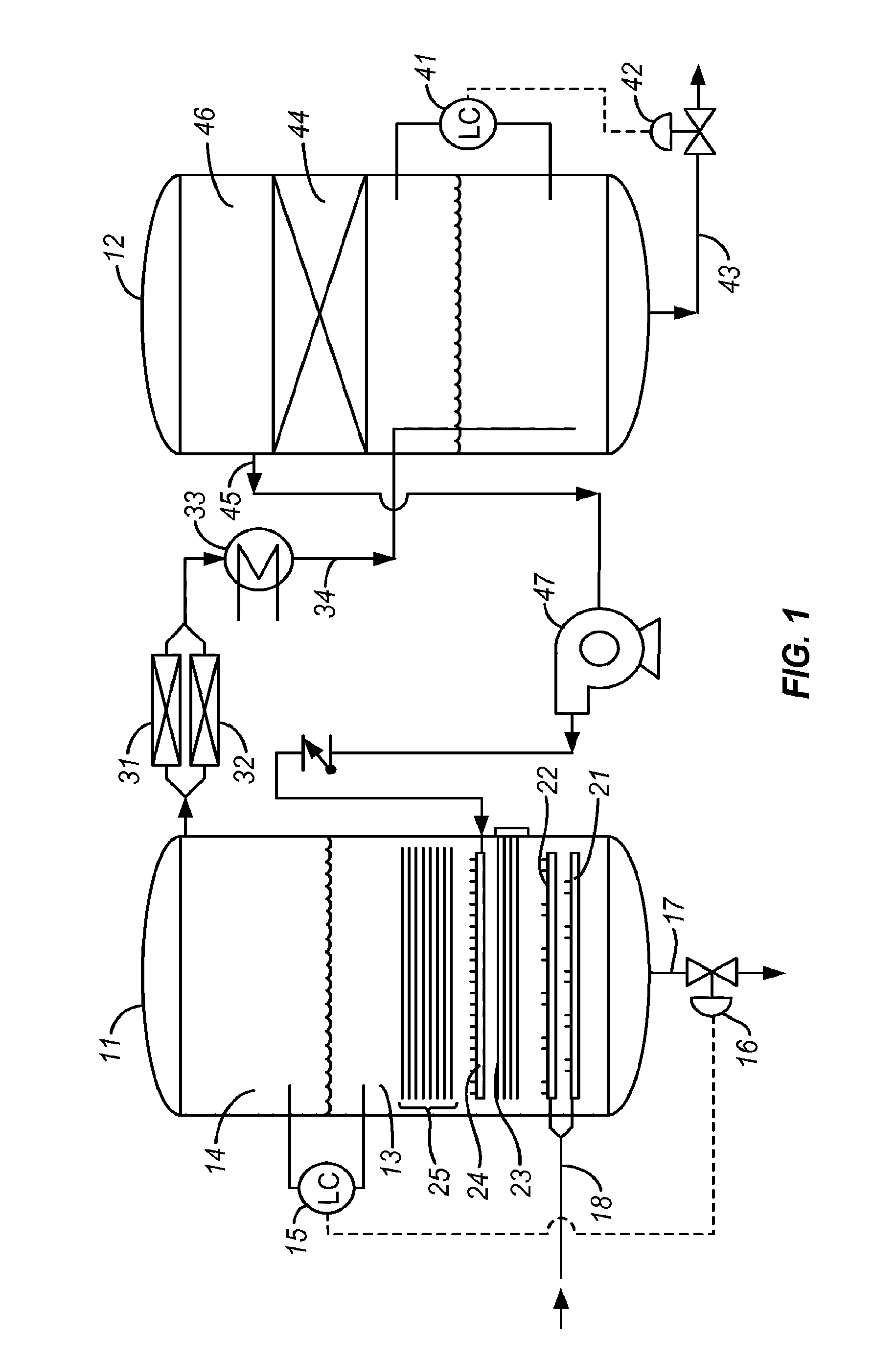
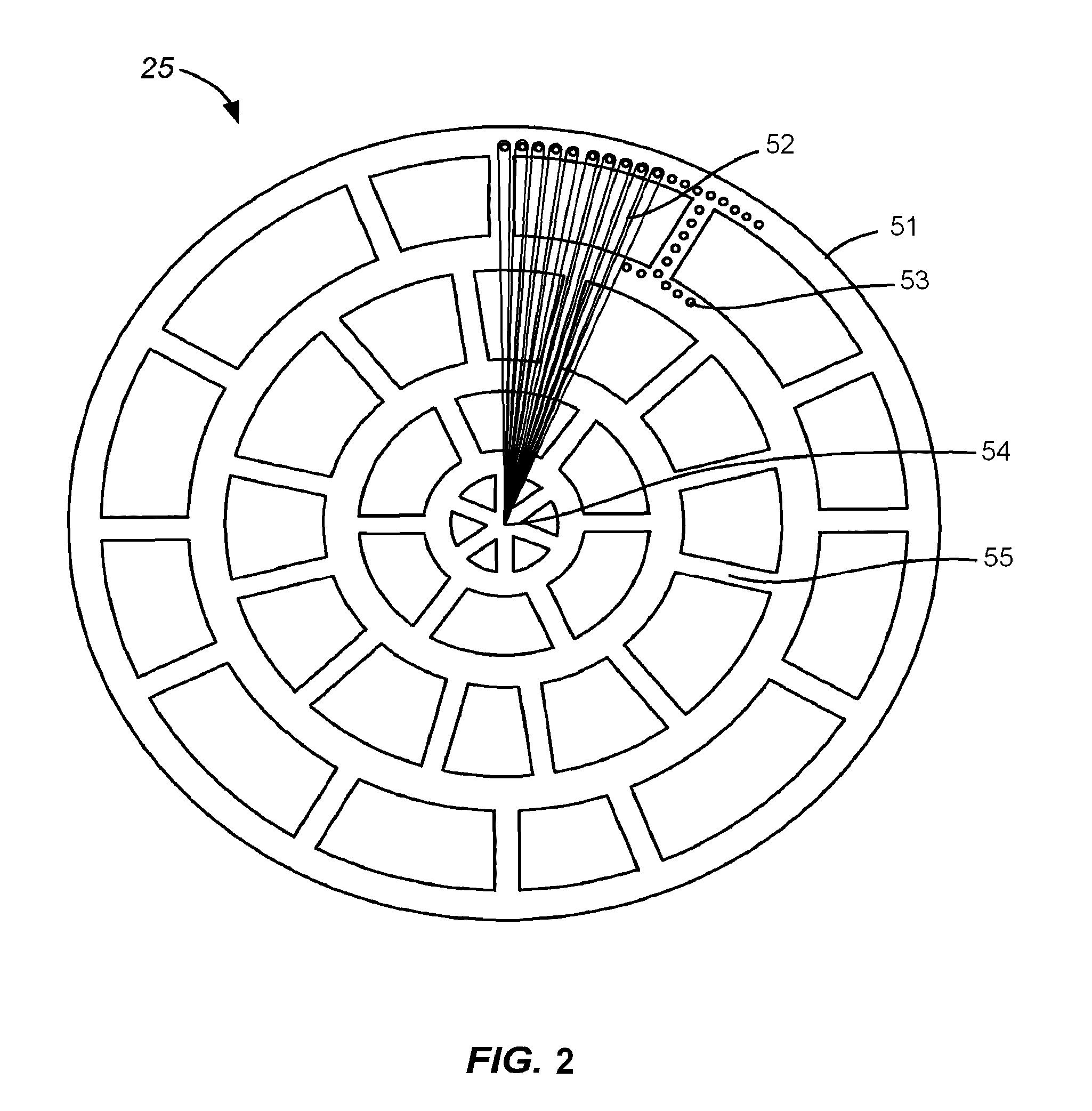
[0025]This example illustrates the present invention as applied to natural gas as the methane-containing gas and diesel oil as the liquid petroleum fraction. The equipment used was as shown in FIG. 1, in which the reaction vessel was a tank with a volumetric capacity of 1,000 gallons (3,785 liters) and a diameter of 6.5 feet (2 meters). The tank was initially charged with 600 gallons (2,270 liters) of diesel fuel maintained at a temperature of 290° F. (143° C.) and a pressure of 6 psig (143 kPa), and natural gas was bubbled through the reactor at a rate of 20,000 SCFH. The catalyst grids consisted of nickel wire, tungsten wire, cobalt wire (an alloy containing approximately 50% cobalt, 10% nickel, 20% chromium, 15% tungsten, 1.5% manganese, and 2.5% iron), and aluminum wire over a gray iron frame. Once fully started, the reactor produced liquid product at a rate of 200 gallons per hour (760 liters per hour), and two gallons of product for every gallon of reaction medium depleted. Al...

example 2

[0031]This example provides the results of emissions tests on two test fuels manufactured in accordance with the present invention and compares these results with results obtained on commercially available No. 2 Ultra Low Sulfur Diesel (ULSD) fuel, all tests conducted in heavy-duty on-road diesel engines using the EPA Transient Cycle Heavy-Duty Test Protocol. The two test fuels were manufactured under the same conditions and in the same equipment as that of Example 1, with kerosene as the liquid petroleum faction in the first test fuel and No. 2 ULSD as the liquid petroleum faction in the second test fuel, and natural gas (95% methane) as the methane-containing gas for both.

[0032]The heavy duty test engine used in the tests was a 1990 model year Caterpillar diesel engine, Model No. 3406B. The test protocol is one that is currently used for emission testing of heavy-duty on-road engines in the United States, pursuant to 40 CFR §86.1333. The test begins with a cold start after parking...


PUM

PropertyMeasurementUnit
temperatureaaaaaaaaaa
electrical resistivityaaaaaaaaaa
temperatureaaaaaaaaaa

Abstract

A methane-containing gas such as natural gas is converted to a clean-burning hydrocarbon liquid fuel in a process wherein the gas is fed to a reaction vessel to contact a metallic catalyst grid that is formed from windings of a transition metal supported on an iron frame immersed in a liquid petroleum fraction, in such a manner that a voltage is generated in the grid between the windings and the frame. Product gas in the vapor phase is drawn from the head space above the liquid level and condensed to form the product fuel.

Description

BACKGROUND OF THE INVENTION[0001]1. Field of the Invention[0002]This invention resides in the field of petroleum-derived liquid fuels and particularly in the conversion of methane to liquid hydrocarbons.[0003]2. Description of the Prior Art[0004]Alternative sources of automotive fuel are in ever increasing demand as crude oil fluctuates in price and as governments and the public at large become increasingly concerned over the gaseous and particulate emissions that the processing of crude oil releases into the atmosphere. Natural gas is an abundant resource in many parts of the world that do not have native supplies of crude oil and in many cases, the cost of extracting natural gas from its natural reservoirs is significantly lower than that of extracting crude oil. For a variety of reasons, however, including its special requirements for transport and storage, natural gas does not offer the full range of uses that are offered by liquid fuels.[0005]This invention provides a means of ...

Claims


Application Information

Patent Timeline
Patent Type & Authority Patents(United States)
IPC IPC(8): C01B3/24
CPCC10G32/02C10G50/00C10L1/04C10L3/10
Inventor GUNNERMAN, RUDOLF W.GUNNERMAN, PETER W.
Owner GUNNERMAN RUDOLF W
Learn More