Operating method and fuel supply system for an internal combustion engine

a fuel supply system and internal combustion engine technology, applied in the direction of combustion-air/fuel-air treatment, electric control, instruments, etc., can solve the problems of great difficulty in operating a gasoline engine using a mixed fuel of gasoline and water, and achieve the effect of reducing nox generation, reducing nox generation, and lowering combustion temperature in the combustion chamber

Inactive Publication Date: 2010-12-14
HONDA MOTOR CO LTD
View PDF14 Cites 8 Cited by
  • Summary
  • Abstract
  • Description
  • Claims
  • Application Information

AI Technical Summary

Benefits of technology

[0025]According to the present invention, a mixing device is used to mix a mixture of ethanol and gasoline with water or mix ethanol and water, so that a mixed fuel in which water, ethanol, and gasoline are mixed causing no phase separation can be obtained. When the mixed fuel is burned in a combustion chamber of an internal combustion engine, the water contained in the mixed fuel is vaporized absorbing heat to lower the combustion temperature in the combustion chamber, so that NOx generation can be reduced. Moreover, according to the present invention, the mixed fuel also contains ethanol, so that the generation of NOx can be noticeably reduced compared with when gasoline only is burned.
[0026]Namely, according to the present invention, a mixed fuel containing water can be used, so that the combustion temperature in a combustion chamber of an internal combustion engine can be lowered. Burning the mixed fuel in such an environment can further reduce NOx generation.
[0027]Moreover, with ethanol and water put in use, the fuel cost and the cost of operating an internal combustion engine can be reduced.

Problems solved by technology

Thus, operating a gasoline engine using a mixed fuel of gasoline and water involves great difficulty.

Method used


Image

  • Operating method and fuel supply system for an internal combustion engine
  • Operating method and fuel supply system for an internal combustion engine
  • Operating method and fuel supply system for an internal combustion engine

Examples


first embodiment

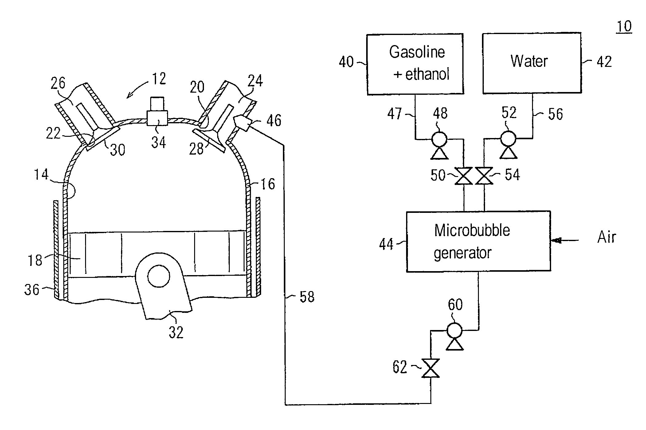
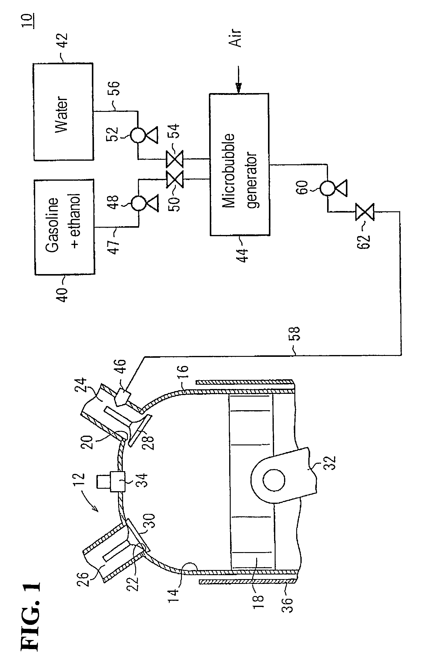
[0032]FIG. 1 is a schematic diagram for explaining an overall configuration of a fuel supply system 10 according to the present embodiment. The fuel supply system 10 is attached to a gasoline engine 12 which is an internal combustion engine.

[0033]First, the configuration of the gasoline engine 12 will be described.

[0034]The gasoline engine 12 includes a cylinder block 16 having a combustion chamber 14 and a piston 18 which slides in the combustion chamber 14. An intake port 20 and an exhaust port 22 are provided in an upper portion of the cylinder block 16 as shown in FIG. 1. The intake port 20 and the exhaust port 22 are connected with a supply pipe 24 and an exhaust pipe 26, respectively.

[0035]The intake port 20 is provided with an intake valve 28 which can close and open the intake port 20. Similarly, the exhaust port 22 is provided with an exhaust valve 30 which can close and open the exhaust port 22.

[0036]FIG. 1 illustrates a connecting rod 32 fitted to a crankshaft, not shown,...

second embodiment

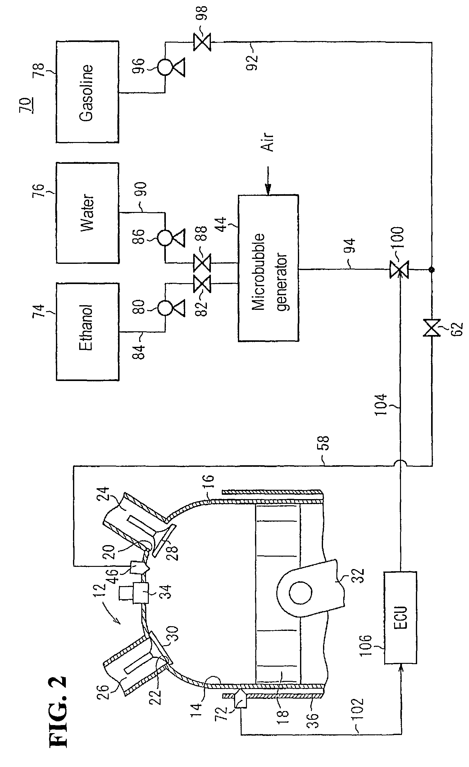
[0054]In the second embodiment, a water temperature sensor 72 (detection means) is installed in the vicinity of a water jacket 36 surrounding the combustion chamber 14. As being described later, the water temperature sensor 72 detects the temperature of the cooling water circulating through the water jacket 36.

[0055]In the fuel supply system 70 according to the second embodiment, ethanol and water are stored separately. Namely, the fuel supply system 70 includes a first tank 74 storing ethanol, a second tank 76 storing water, a third tank 78 storing gasoline, a microbubble generator 44 connected to the first and second tanks 74 and 76, and a fuel injection valve 46 which injects a mixed fuel containing a mixture fed from the microbubble generator 44 and gasoline. An end portion of the fuel injection valve 46 is implanted in the cylinder block 16 such that the mixed fuel can be injected directly into the combustion chamber 14 through the end portion.

[0056]In the second embodiment, th...


PUM


Abstract

A fuel supply system attached to the gasoline engine includes a first tank storing a mixture of gasoline and ethanol, a second tank storing water, a microbubble generator connected to the first and second tanks, and a fuel injection valve connected to the microbubble generator. The mixture and the water are mixed in an environment where microbubbles generated by operation of the microbubble generator are supplied. The mixed fuel thus prepared is injected, via the fuel injection valve, into a supply pipe connected to a cylinder block which is included in the gasoline engine. The mixed fuel is then mixed with the air flowing through the supply pipe to be supplied into a combustion chamber. The resulting configuration lowers the combustion temperature in the gasoline engine so as to reduce the amount of NOx contained in exhaust gas.

Description

CROSS-REFERENCE TO RELATED APPLICATION[0001]The present application claims priority under 35 U.S.C. §119 to Japanese Patent Application No. 2006-323362, filed Nov. 30, 2006, the entire contents of which are hereby incorporated by reference.BACKGROUND OF THE INVENTION[0002]1. Field of the Invention[0003]The present invention relates to an internal combustion engine operating method in which, to obtain motive power, an internal combustion engine is driven by burning a mixed fuel in a combustion chamber thereof and a fuel supply system for supplying a mixed fuel to a combustion chamber of an internal combustion engine.[0004]2. Description of Background Art[0005]Out of growing concern about environmental problems, use of a mixed fuel of gasoline and ethanol as a fuel for gasoline engines (internal combustion engines) mounted on automobiles is being studied. When a gasoline engine is operated using the mixed fuel, the amounts of carbon monoxide, hydrocarbon, and nitrogen oxide (NOx) cont...

Claims


Application Information

Patent Timeline
Patent Type & Authority Patents(United States)
IPC IPC(8): F02B47/02
CPCF02B47/02F02D41/0025F02M25/0228F02M25/0227F02D19/081F02D19/084F02D19/0673F02D35/027F02D2200/0612Y02T10/36F02D19/0655F02D19/0665F02M25/0225Y02T10/30
Inventor KAWAMATA, NORIYUKI
Owner HONDA MOTOR CO LTD
Why Eureka
Try Eureka