Dynamically variable metamaterial lens and method

a metamaterial and dynamic field technology, applied in the field of dynamic field, can solve the problems of limited number of special lens materials, limited material effective for terahertz range optical elements, and small dependence of materials on frequency or wavelength

Inactive Publication Date: 2011-01-04
NAVY THE UNITED STATES OF AMERICA SEC OF THE
View PDF3 Cites 50 Cited by
  • Summary
  • Abstract
  • Description
  • Claims
  • Application Information

AI Technical Summary

Benefits of technology

[0016]a substrate and a capacitance tuned split ring resonator formed on the substrate. The capacitance tuned split ring resonator includes a resonating structure having a gap and formed of an electrically conductive material. A region of photo-capacitive material is formed in close proximity to the re

Problems solved by technology

However, these materials display a small dependence on frequency or wavelength, noticed as chromatic aberration.
A limited number of special lens materials are effective in the infrared range.
Materials effective for terahertz range optical elements are more limited and reflective optics are often used instead of refractive lenses because of absorption effects.
These materials are effectiv

Method used


Image

  • Dynamically variable metamaterial lens and method
  • Dynamically variable metamaterial lens and method
  • Dynamically variable metamaterial lens and method

Examples


example 1

[0104]FIG. 6 shows a photo-capacitance spectrum of steady state photo-capacitance for GaAs measured at 77° K. Illuminating photon energy was plotted against magnitude of photo-capacitance. Three distinct levels (605, 610, 615) are shown, one for each charge state of EL2. These are localized states with discrete energy levels. The energies are referenced to the valence band. It was noted that the 0.77 eV value was within the range of experimental error of the accepted value of 0.73 eV at 77° K. Excitation of electrons from the valence band was used to reduce the EL2 energy level excitation states. The band gap for GaAs is 1.424 eV (A=0.89 μm) at 300° K. The band gap energy is the energy required to excite an electron from the valence band to the conduction band in FIG. 6. For the first type of EL2 transition with threshold energy of 0.54 eV (λ=2.3 μm), an electron is excited into an EL2(++) state, forming EL2(+) and there is a 10% change in capacitance. For the second type of transit...

example 2

[0105]FIG. 7 shows the effect of varying the intensity of the controlling electromagnetic radiation on the capacitance of an undoped SI GaAs filled capacitor. Gate voltage was plotted versus capacitance. A tungsten lamp was the source of the controlling electromagnetic radiation. The lamp produced a broad spectrum ranging from the infrared to visible light. There was about a 200% change in capacitance between the value in the region 705 labeled “dim light” and the value in the regions 710, 715 labeled “bright light.” As the level of the controlling electromagnetic radiation was varied, the gate voltage was varied linearly with time. As shown, the capacitance was essentially independent of gate voltage above approximately 5 eV. Typical capacitances for this type of experiment were found to range from 0.035 pF / mm2 to 0.118 pF / mm2 for a 1 mm thick undoped SI-GaAs sample.

example 3

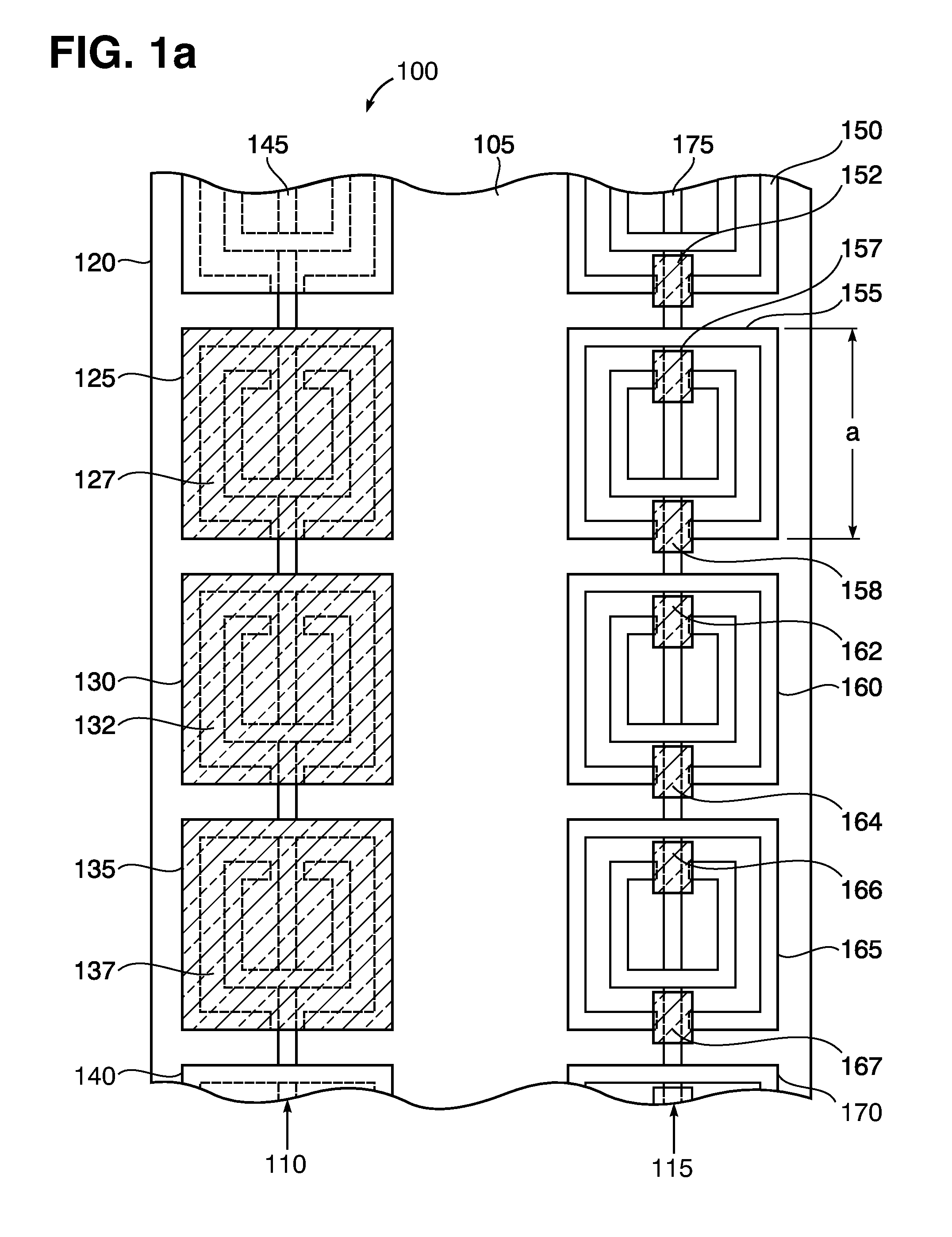
[0106]An SRR was constructed according to FIG. 1a. The total inductance of the SRR was calculated to be: Ltot=4.9 nano-Henries. The measured resonance frequency was: f=11 GHz. The formula:

f=1 / 2π(LtotC)1 / 2,  Eq. (6)

yielded C=43 femto-Farads for the capacitance of the outer SRR only, for simplicity, neglecting any effects of the inner structure. In this case, a change of capacitance ΔC=8.6 femto-Farads yields a 1.1 GHz reduction in resonant frequency. Similarly, an SRR was constructed according to FIG. 4, the total inductance was Ltot=5.8 nano-Henries and the resonant frequency was f=8.5 GHz. This gave a capacitance of C=61 femto-Farads. Thus a shift of 10% in frequency requires a 20% change in capacitance, or ΔC=12 fF. It is apparent that capacitive tuning concept can be scaled to other wavelengths.


PUM


Abstract

A dynamically variable lens is made from actively tunable electromagnetic metamaterial cells. The lens operates on electromagnetic radiation including: radio frequency waves, microwaves, teraherz waves, near infrared waves, infrared waves and visible waves. The focal length of the lens is changed at a selected frequency. In the alternative, the frequency of radiation operated on is changed as a function of time. A third alternative provides precise control of the index of refraction of the lens. The index of refraction is varied progressively across the lens from one edge to the opposite edge causing the radiation to be directed at an angle.

Description

CROSS-REFERENCE TO RELATED APPLICATIONS[0001]This application is a continuation-in-part of U.S. patent application Ser. No. 11 / 504,859 filed Aug. 16, 2006, for an Actively Tunable Electromagnetic Metamaterial, incorporated herein by reference. Ser. No. 11 / 504,859 and this application claim the benefit of U.S. Provisional Application No. 60 / 713,615, filed Aug. 31, 2005, which is incorporated herein by reference.STATEMENT OF GOVERNMENT INTEREST[0002]The invention described herein may be manufactured and used by or for the Government of the United States of America for governmental purposes without the payment of any royalties.BACKGROUND OF THE INVENTION[0003]1. Field of the Invention[0004]The invention relates to a dynamically variable lens made of an electromagnetic metamaterial. The invention also relates to a method of dynamically varying a metamaterial lens. The invention also relates to a resonance frequency tunable system.[0005]2. Discussion of the Related Art[0006]Lenses that o...

Claims


Application Information

Patent Timeline
IPC IPC(8): G02F1/03
CPCB82Y20/00G02B1/007G02F1/0126H01Q15/0086G02F1/01716G02F2202/30G02F2203/13
Inventor RULE, DONALD W.BOULAIS, KEVIN A.SANTIAGO, FRANCISCO
Owner NAVY THE UNITED STATES OF AMERICA SEC OF THE
Why Eureka
Try Eureka