
Dialysis systems having air traps with internal structures to enhance air removal

Active Publication Date: 2011-02-22
BAXTER HEALTHCARE SA +1
View PDF175 Cites 37 Cited by
  • Summary
  • Abstract
  • Description
  • Claims
  • Application Information

AI Technical Summary

Benefits of technology

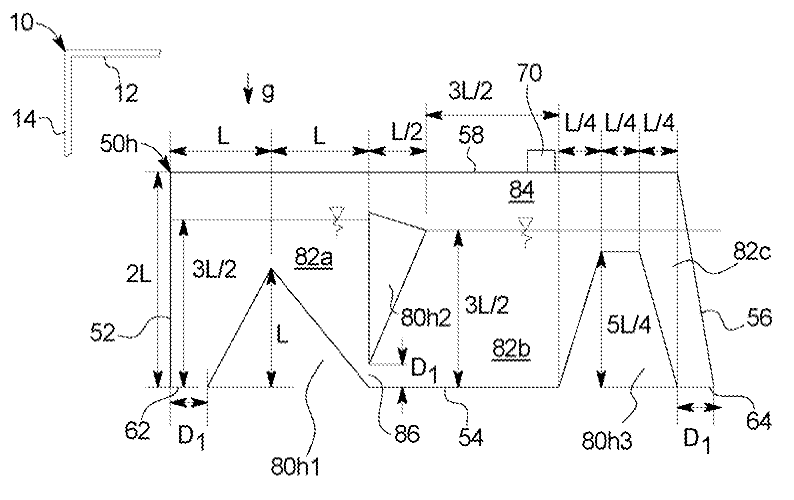
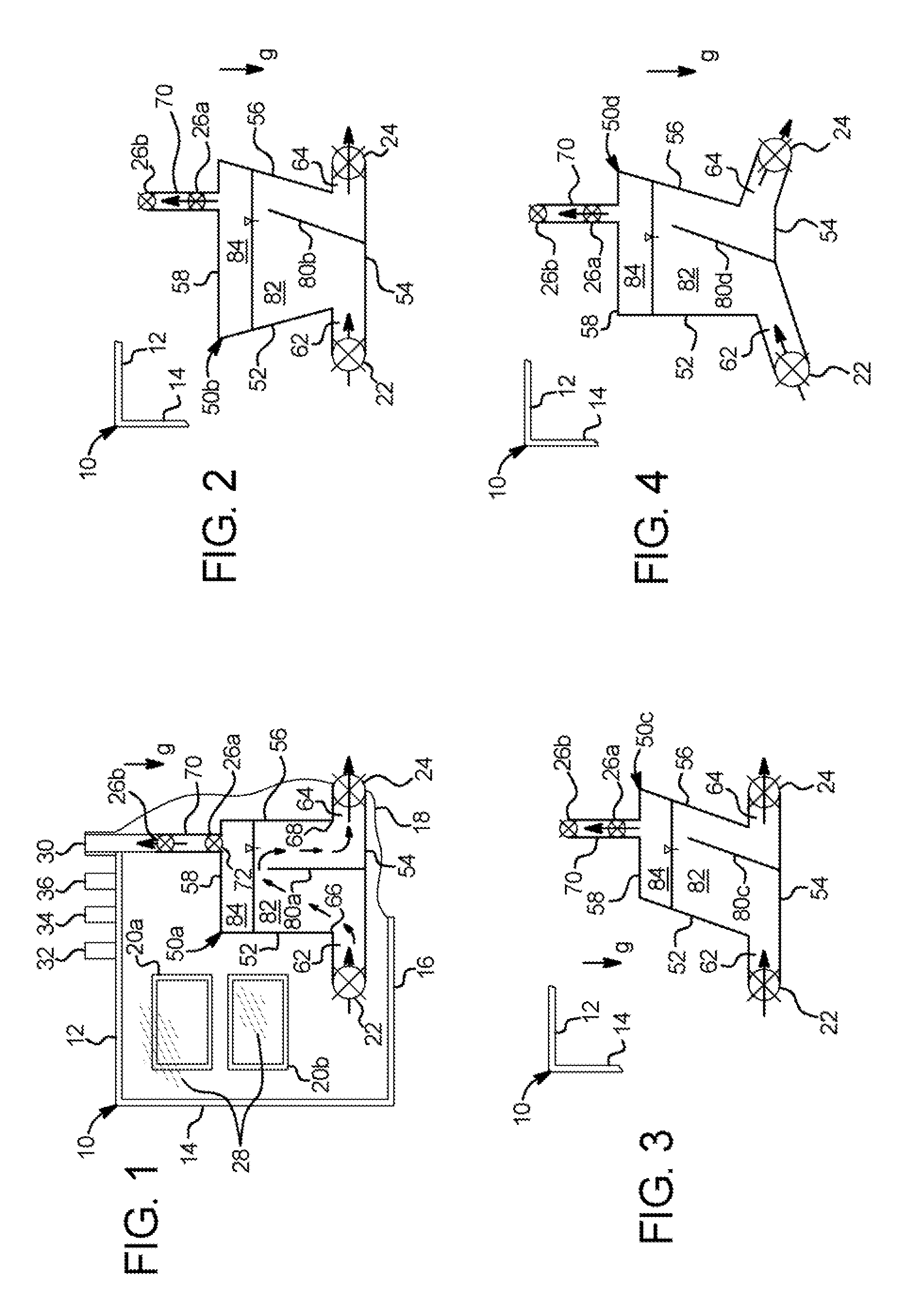
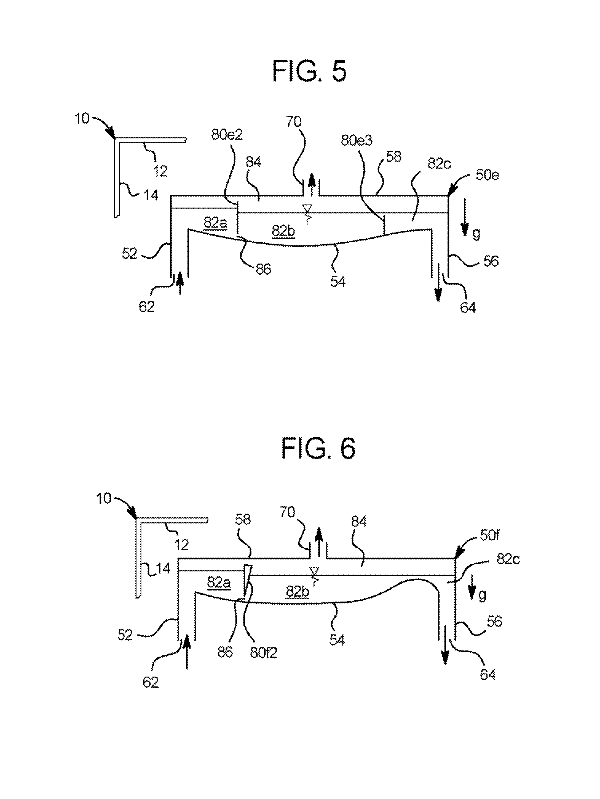
In one embodiment, the air separation chamber is configured with respect to the other components of the disposable cassette such that when the cassette is loaded into the dialysis instrument, the fluid inlet and fluid outlet are located towards a bottom or bottom wall of the air separation chamber, while the air outlet is located at or near the top of the dialysis instrument. Such configuration allows buoyancy forces to lift air bubbles from the dialysis fluid to the top of the air separation chamber for venting.
The dialysis cassette in one embodiment includes a rigid portion, which can be a hard plastic. The rigid portion is formed to have pump chambers (e.g., for diaphragm pumps) or pump tubing (for peristaltic pumping), fluid pathways and valve chambers. The rigid portion also defines some or all of the air separation chamber. It is contemplated that the disposable cassette will have flexible sheeting welded to one or both sides of the rigid portion of the cassette. The flexible sheeting allows a pneumatic or mechanical force to be applied to the pump chambers (e.g., diaphragm) and valve chambers to operate those chambers. It is also contemplated that at least one outer surface of the air separation chamber consumes a portion of one or both flexible sheets. In addition, one or both sides of the dialysis cassette can be rigid.
In still a further alternative embodiment, the baffle is configured to float within the air separation chamber. That is, the baffle is not connected to any of the walls of the rigid portion of the disposable cassette and instead is moveable independently within the air separation chamber. For example, the air separation chamber can include a plurality of spheres or other shaped members, which are too large to fit through any of the dialysate inlet, dialysis fluid outlet or air chamber openings. The plural spheres provide increased surface contact area with the fluid to better remove air bubbles from the liquid. Additionally, the free motion accorded to the baffle (or plurality of baffles) allows their potion to disrupt air bubbles that may have accumulated through surface tension onto various surfaces within the chamber or on themselves. This disruption allows the bubbles to be coalesced into larger bubbles and carried to the air / fluid interface of the chamber for venting. Alternatively, a loose fitting geometry, such as a coiled or twisted strip of plastic, is moveable within the air separation chamber to provide a large contact surface area with the dialysis fluid and to route fluid towards the air / fluid interface of the chamber where bubbles can be separated from the fluid. To this end, the spheres or other shaped members can be textured to provide even additional surface contact area. In an alternate stationary geometry, the geometry can be rigid on the air trap.
It is further contemplated to provide a nozzle at the air separation chamber inlet, which causes the inlet dialysis fluid to form a spray or mist, which further aids in removing air from the dialysis fluid. Still further, it is contemplated to provide a vibrator, such as an ultrasonic or mechanical vibrator within the disposable cassette, which contacts a portion of the disposable set, such as a portion of the disposable cassette. The vibrator vibrates the disposable cassette to further aid in dislodging air bubbles from the dialysis stream and to aid in their coalescence that increases the bubbles' buoyancy force, thereby inducing them to float to the surface of the chamber for venting. In an embodiment, the ultrasonic or other type of vibrator is positioned within the dialysis instrument to contact the disposable cassette at the air separation chamber. The vibrator provides a force in addition to buoyancy to separate air from the fluid, forming an air separation area. The air separation area attacks entrained air on multiple fronts, one using the above described baffles and another using the ultrasonic or other type of vibration. It is further contemplated to add the nozzle at the inlet to this two-pronged air separation attack to form a three-pronged attack.
It is accordingly an advantage of the present disclosure to provide improved air separation chambers for the removal of air from the dialysis fluid or blood flowing through a disposable dialysis fluid apparatus.

Problems solved by technology

Air can also signal a leak in the disposable unit.

Method used


Image

  • Dialysis systems having air traps with internal structures to enhance air removal
  • Dialysis systems having air traps with internal structures to enhance air removal
  • Dialysis systems having air traps with internal structures to enhance air removal

Examples


Embodiment Construction

Referring now to the drawings and in particular to FIG. 1, dialysis cassette 10 having air trap 50 illustrates one embodiment of the present disclosure. Dialysis cassette 10 is operable with any type of dialysis instrument, such as a peritoneal dialysis instrument, hemodialysis, hemofiltration, hemodiafiltration or continuous renal replacement therapy instrument. Dialysis cassette 10 can hold a dialysis fluid, such as dialysate or blood. The dialysis fluid can be premixed or cassette 10 can carry a component of dialysate such as a dialysate concentrate.

Dialysis cassette 10 in one embodiment is part of a disposable set, which includes one or more supply bag, a drain bag, a heater bag, and tubing running from those bags (not illustrated) to dialysis cassette 10. Dialysis cassette 10 in one embodiment is disposable, however, dialysis cassette 10 could be cleaned for multiple uses in which case the air traps described herein are used multiple times. Dialysis cassette 10 includes a rigid...


PUM

PropertyMeasurementUnit
Angleaaaaaaaaaa
Shapeaaaaaaaaaa
Widthaaaaaaaaaa

Abstract

A dialysis fluid cassette includes a rigid portion defining first and second valve chambers, the rigid portion further defining an air separation chamber in fluid communication with the first and second valve chambers, the air separation chamber including a baffle and structured such that when the cassette is placed in a dialysis instrument, (i) the baffle extends upwardly from a bottom of the air separation chamber and (ii) first and second openings to the air separation chamber, communicating fluidly and respectively with the first and second valve chambers, are located near the bottom of the air separation chamber, such that the dialysis fluid is forced up one side of the baffle and down the other side of the baffle when flowing through the air separation chamber.

Description

BACKGROUNDThe examples discussed below relate generally to medical fluid delivery. More particularly, the examples disclose systems, methods and apparatuses for dialysis such as hemodialysis (“HD”) automated peritoneal dialysis (“APD”).Due to various causes, a person's renal system can fail. Renal failure produces several physiological derangements. It is no longer possible to balance water and minerals or to excrete daily metabolic load. Toxic end products of nitrogen metabolism (urea, creatinine, uric acid, and others) can accumulate in blood and tissue.Kidney failure and reduced kidney function have been treated with dialysis. Dialysis removes waste, toxins and excess water from the body that normal functioning kidneys would otherwise remove. Dialysis treatment for replacement of kidney functions is critical to many people because the treatment is life saving.One type of kidney failure therapy is Hemodialysis (“HD”), which in general uses diffusion to remove waste products from a...

Claims


Application Information

Patent Timeline
IPC IPC(8): B01D19/00
CPCA61M1/1658A61M1/3627B01D19/0042A61M1/288A61M2205/12A61M2205/128A61M1/155A61M1/1565A61M1/152
Inventor PRISCO, MICHAEL R.YARDIMCI, ATIF M.ACIKGOZ, SERHANLAIRD, JAMES C.MALIEKKAL, SHINCY J.ROHDE, JUSTIN B.
Owner BAXTER HEALTHCARE SA
Learn More