Gun drill

a gun drill and drill bit technology, applied in the field of gun drills, can solve the problems of insufficient cutting efficiency and durability of the conventional gun drill, and the difficulty in polishing the cutter with a small diameter, so as to prevent vibration of the cutter head, and reduce the difficulty of polishing.

Inactive Publication Date: 2011-03-08
YUNITAKKU
View PDF14 Cites 7 Cited by
  • Summary
  • Abstract
  • Description
  • Claims
  • Application Information

AI Technical Summary

Benefits of technology

[0011]According to the gun drill as set forth in the first aspect of the invention, since, in a deep boring process, the cutter head is brought into sliding contact with the inner circumference of a cutting bore at the peripheral portion thereof having higher hardness than a cemented carbide alloy and having less toughness while cutting a workpiece by means of the blade portion, made of a cemented carbide alloy, of the cutter head, and the rigid slide-contacting portion thereof stably receives a reaction force in line with cutting, minute shake or swing such as vibrations of the cutter head can be prevented from occurring, and the cutting rate can be remarkably increased to achieve a high working efficiency. Further, the blade portion can be prevented from being broken or worn, wherein since the service life of the blade can be prolonged, and the frequency of re-polishing for re-use of a small-diameter cutter head can be remarkably reduced, the labor, time and costs therefor can be greatly reduced.
[0012]According to the second aspect of the invention, since the guide pad of the cutter head is composed of the above-described dissimilar material, it becomes possible to manufacture the corresponding cutter head simply and easily in view of structure.
[0013]According to the third aspect of the invention, since the dissimilar material is sintered ceramic or cermet, there are advantages in that, in comparison with a gun drill the entirety of the cutter head of which is made of a cemented carbide alloy, the cutting rate can be remarkably increased and the service life of the blades can be extended.
[0014]According to the fourth aspect of the invention, there are advantages in that, since the above-described sintered ceramic is composed of a sintered body of a specified component, the cutting rate can be increased, and the service life of the blades can be extended.

Problems solved by technology

In this connection, the cutting efficiency and durability are insufficient with the conventional gun drill.
In particular, labor and time required for polishing the cutter having a small diameter become a problem.

Method used


Image

  • Gun drill
  • Gun drill
  • Gun drill

Examples


examples

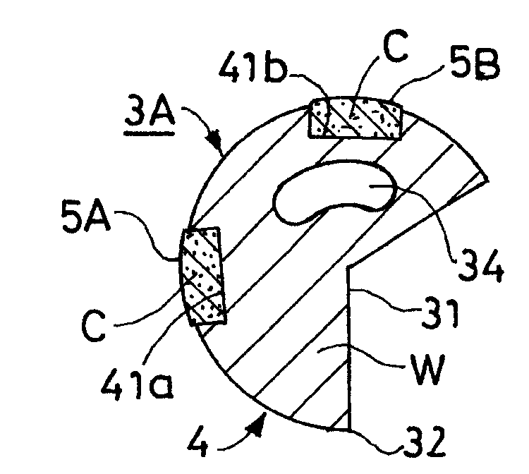
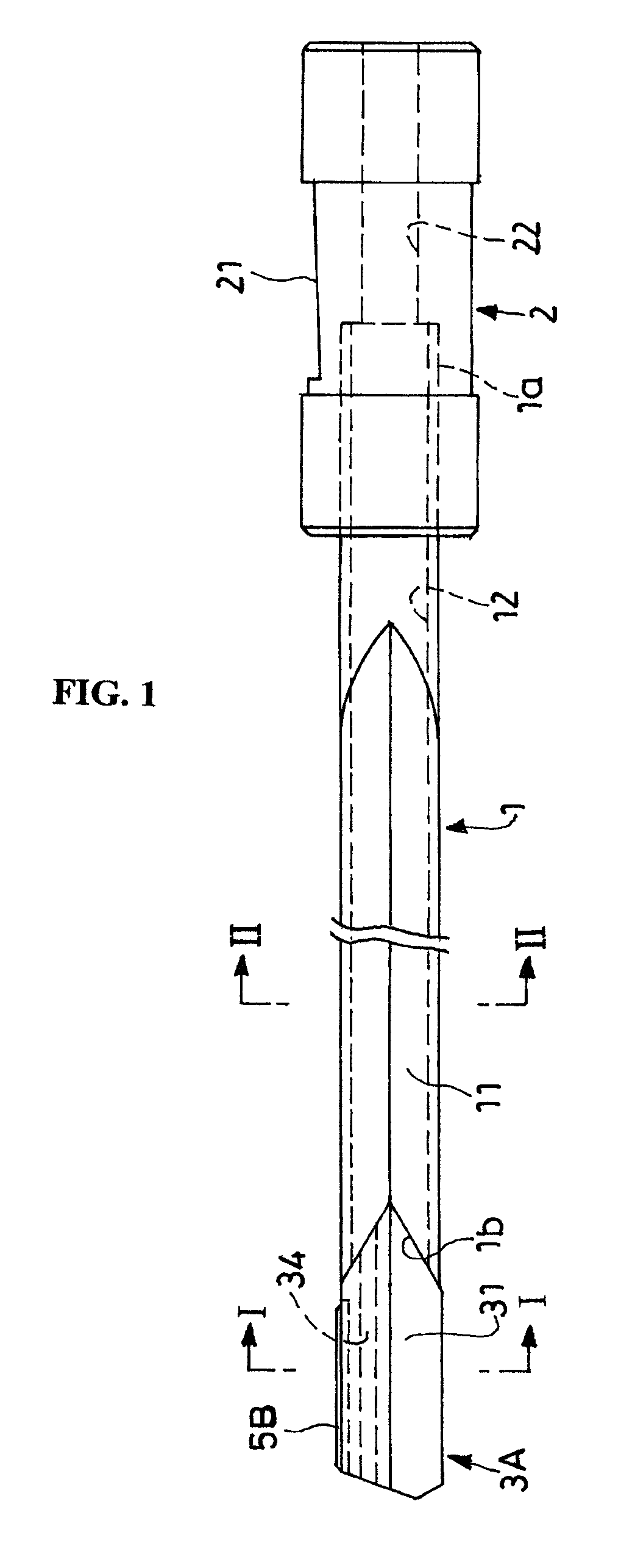
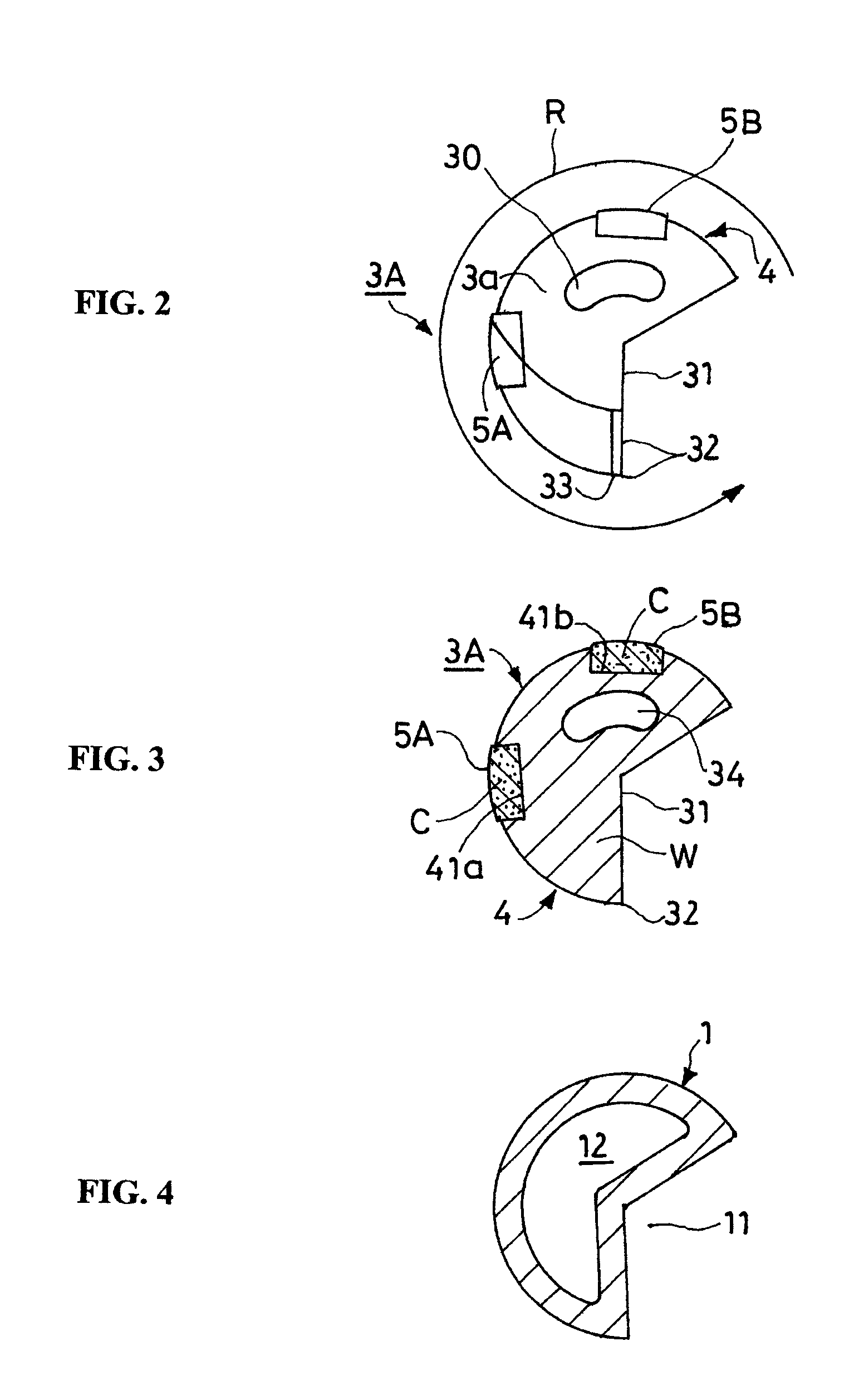
[0042]Gun drills G1 through G3 the respective parts of which are the following dimensions and are composed of the following materials in the modes shown in FIG. 1 through 4, gun drill G4 in which the guide pads 5A and 5B are substituted by a thick plate-shaped component 8 having the surface shown in FIG. 7 made of a micro-crystal diamond sintered body, and gun drill G0 of the same composition excepting that the entirety of the cutter head is composed of a cemented carbide alloy, are used. In respective cases, non-water-soluble cutting oil is supplied as the coolant at a pressure level of 50 kg / cm2 at a flow rate of 35 liters per minute, and deep-hole drilling of a calibration of 10 mm is carried out on a workpiece of S50C (cold-drawn steel, HB200 through 300), wherein possible cutting rates are compared, and service lives of the respective cases are investigated based on the accumulated cutting bore depth until the blade portion reaches the wearing degree at which re-polishing there...


PUM

PropertyMeasurementUnit
widthaaaaaaaaaa
angleaaaaaaaaaa
lengthaaaaaaaaaa

Abstract

A gun drill having excellent cutting efficiency, having high deep-hole drilling efficiency, and having a prolonged blade service life has a cutter head having a coolant discharge port communicating with a coolant supplying path at the distal end face at the distal end of a hollow shank portion having a cutting chip discharge groove, whose section along the lengthwise direction is V-shaped, on the outer surface and having the interior thereof made into a coolant supplying path, wherein a blade portion of the cutter head is made of cemented carbide alloy, and at the same time, the guide pads and that are brought into sliding contact with the inner circumference of a cutting bore are composed of a dissimilar material having higher hardness than the cemented carbide alloy.

Description

FIELD OF THE INVENTION[0001]The present invention relates to a gun drill used for deep-hole drilling.BACKGROUND OF THE INVENTION[0002]Although various systems such as a gun drilling system, an ejector system (double tube system), a single tube system, etc., have been publicly known as a deep-hole drilling system, the gun drilling system is suitable for deep-hole drilling of a small diameter. That is, the gun drill system generally employs a gun drill having a cutter head, the outer cross section of which is a notched circle (⅔ through ¾ circle), provided at the distal end of a hollow shank portion having the same notched circle, carries out cutting while supplying coolant, which is supplied through the interior of the hollow shank portion, from a coolant discharge port at the distal end face of the cutter head to a cutting portion, and discharges cutting chips, which are generated in line with the cutting, to the exterior through a cutting chip discharge groove whose section is V-sh...

Claims


Application Information

Patent Timeline
Patent Type & Authority Patents(United States)
IPC IPC(8): B23B51/00
CPCB23B51/0486B23B2226/125B23B2226/18B23B2251/424Y10T408/81Y10T408/455Y10T408/78Y10T408/5586B23B2251/56B23B51/066B23B51/06B23B51/00
Inventor NOMURA, TAKUJI
Owner YUNITAKKU
Why Eureka
Try Eureka