Ionization method and apparatus using electrospray

a technology of electrospray and ionization method, which is applied in the direction of scanning probe technique, separation process, instruments, etc., can solve the problems of limited spatial resolution, difficult to reduce the beam diameter of the laser beam to less than several tens of microns, and limited spatial resolution

Active Publication Date: 2011-03-08
UNIVERSITY OF YAMANASHI
View PDF14 Cites 15 Cited by
  • Summary
  • Abstract
  • Description
  • Claims
  • Application Information

AI Technical Summary

Benefits of technology

[0015]The present invention provides an ionization method and apparatus in which biological tissue and the like without pre-treatment can be adopted as a sample of interest and, moreover, it is possible to desorb and ionize the sample ions under atmospheric pressure.
[0016]Further, the present invention provides an ionization method and apparatus in which a miniscule sample can be handled without causing clogging and the like and, moreover, it is possible to produce an electrospray efficiently.
[0017]Further, the present invention provides an ionization method and apparatus capable of producing the electrospray phenomenon even with regard to a liquid biological sample and sample having a high salt concentration.
[0018]Further, the present invention provides an ionization method and apparatus in which imaging having a resolution on the nanometer (nm) order is possible.
[0023]With probe (needle) electrospray according to the present invention, the probe is oscillated to thereby capture the sample at the tip of the probe and produce the electrospray. Since a probe (needle) is used, clogging does not occur. If a probe having a sharp tip is used, an electrospray can be produced efficiently (the effect of the electric field is enhanced to the limit). Since the probe is oscillated, the amount of sample taken up by the probe can be enlarged; the higher the oscillation frequency is made, the more the amount of sample captured. Furthermore, if a probe (needle) having a tip diameter on the atomic level is used, then a nanometer level for the diameter of the needle tip can be achieved to the maximum degree. As a result, the electrospray phenomenon can be produced even for samples having a high salt concentration. The voltage applied to the probe is applied so as to produce a potential difference between the probe and another member, e.g., a part of the mass spectrometer or a member related thereto (an orifice or skimmer, etc., having an ion sampling hole, or a sampling tube or capillary, etc.), the sample holding means (sample) or a member related thereto (depending upon the case, there are instances where it is desired to so arrange it that almost no potential difference is produced between the probe and sample holding means, although various modes of applied voltage will be described later).
[0025]In the case of visible laser light [e.g., a frequency-doubled (532 nm) YAG laser], a surface plasmon is induced on the metal (probe) surface irradiated with the laser beam. The surface plasmon propagates along the probe surface toward the tip and intensifies the electric field strength in the vicinity of the probe tip. Accordingly, desorption ionization of sample molecules by electrospray is intensified. In a case where use is made of infrared laser light, promotion of sample drying and efficiency of ion desorption from a droplet are improved by heating the sample, which has been captured in the vicinity of the probe tip, and the metal surface. Further, owing to the effect of heating, non-covalent-bonded compounds and the like can be dissociated selectively into individual subunits. With infrared laser irradiation, it is possible to observe the dissociation of a non-covalent-bonded compound, which plays an important role in biological reactions.

Problems solved by technology

It is difficult to reduce the beam diameter of the laser beam to less than several tens of microns with these methods, and since aberration extends over a wide area, the limit on spatial resolution is 50 μm.
On the other hand, however, spatial resolution is limited since the crystal size of the matrix applied to the sample exceeds 100 μm.
However, the energy of the ions is large (10 to 20 keV), incident ions penetrate into the sample over a depth of several hundred angstroms and the sample sustains damage.
Consequently, the yield of ions from a readily decomposed sample such as a biological sample declines rapidly with time.
Since the sample desorbed is limited to the molecules in the proximity of the surface, the detection sensitivity of ions with respect to biologically related samples is low.
However, a spatial resolution of less than a micron is difficult to obtain because the current of the primary ion beam is small and the ion beam diameter is greater than several microns.
These SIMS methods are all difficult to apply to high-mass molecules such as biological macromolecules.
With these methods, however, it is difficult to obtain a resolution of less than a micron owing to the fundamental limitations thereof.
In addition, since the sample must be introduced into the vacuum system of a mass spectrometer that operates only under high vacuum, preliminary treatment is very troublesome.
Accordingly, no matter what improvements are applied to the conventional MALDI or SIMS methods, it is nearly impossible to realize a resolution of less than a micron so long as these are adopted as the basic techniques.
Owing to the viscosity of the liquid, it is fundamentally impossible to impart this droplet with a size of less than a micrometer or submicrometer.
Thus, droplet size capable of being produced by electrospray is decided in the manner of a natural occurrence and it is difficult to achieve a further reduction in size.
There are many limitations such as clogging.
It is difficult to produce a spray and handling is troublesome.
Furthermore, with conventional electrospray, an increase in salt concentration results in spraying difficulty and there is a sudden decline in desorption efficiency of ions into the gaseous phase.

Method used


Image

  • Ionization method and apparatus using electrospray
  • Ionization method and apparatus using electrospray
  • Ionization method and apparatus using electrospray

Examples


first embodiment

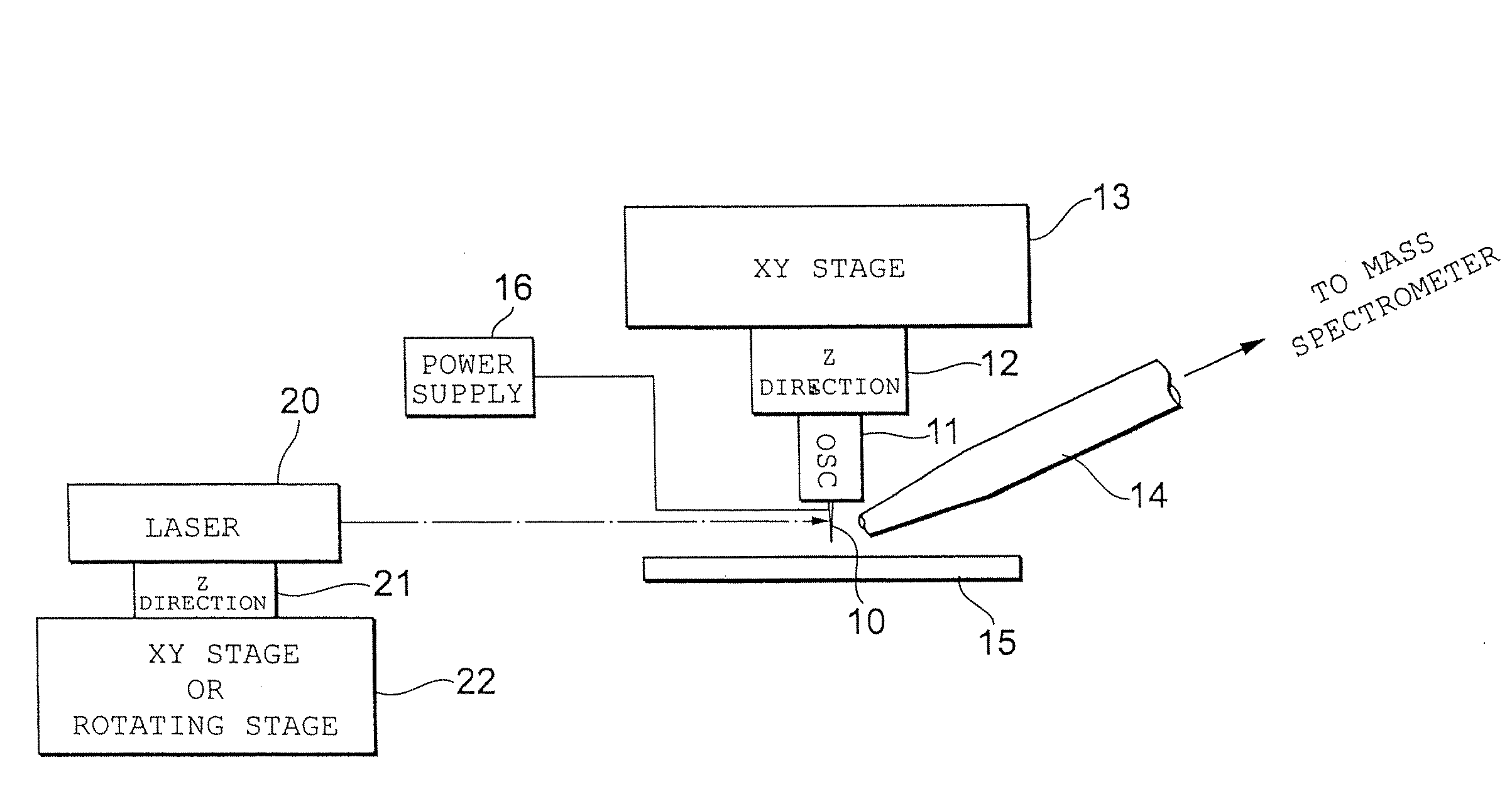
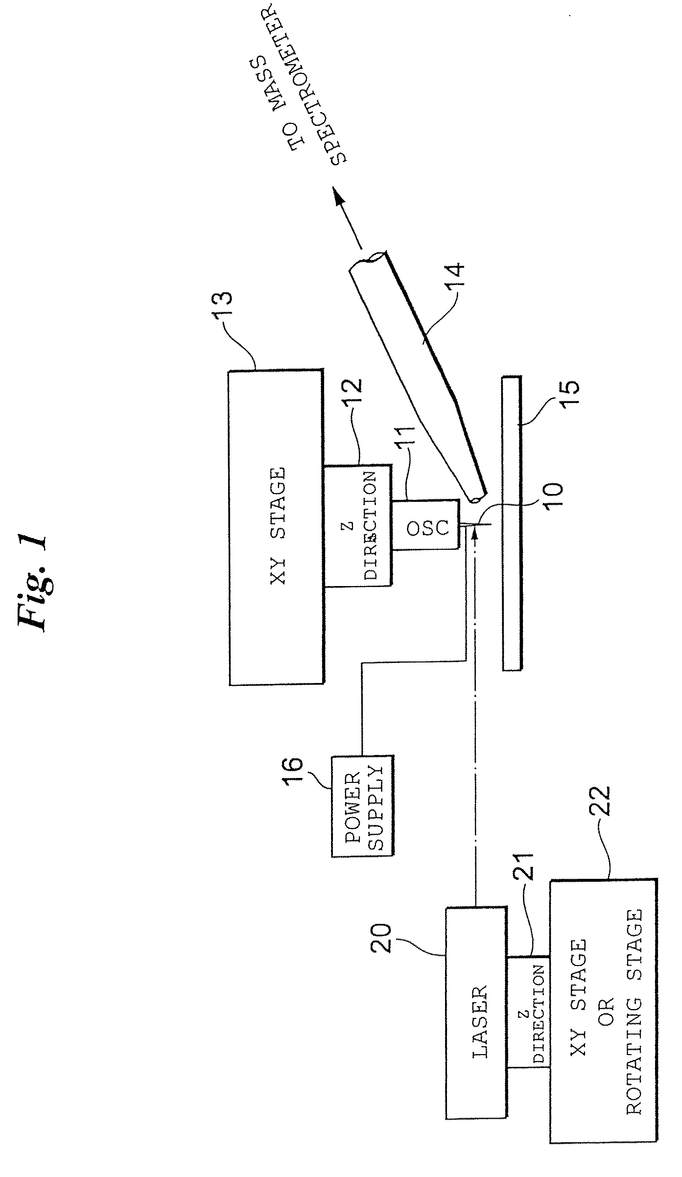
[0063]FIG. 1 illustrates the configuration of an ionization apparatus capable of imaging according to a

[0064]This ionization apparatus is capable of operating under atmospheric pressure. Sample ions desorbed and ionized from a sample by this ionization apparatus are introduced to a mass spectrometry apparatus. Although an orthogonal time-of-flight mass spectrometer can be mentioned as an example of the mass spectrometry apparatus, the present invention is also applicable to a mass spectrometry apparatus such as a (linear) ion-trapping mass spectrometry apparatus.

[0065]A sample table 15 is secured to the ionization apparatus at a suitable location. A biological sample is placed on the sample table 15 as is (without being subjected to a pre-treatment, as in the case of MALDI). For the sake of convenience, the upper surface of the sample table 15 is adopted as the XY plane and the direction perpendicular thereto is adopted as the Z direction.

[0066]An XY stage 13 is placed above the sam...

second embodiment

[0080]FIG. 4 illustrates a This embodiment has a configuration ideal for biological samples.

[0081]A high vacuum is maintained in a mass spectrometry apparatus 40. A portion of the mass spectrometry apparatus 40 into which ions are introduced is provided with a skimmer 41. The skimmer 41 has a very small hole (ion introduction port) 41a.

[0082]An electrospray capillary 30 is placed at the front face of the skimmer 41 of the mass spectrometry apparatus 40 (in a space at atmospheric pressure outside the mass spectrometry apparatus 40). The capillary 30 is connected to the outlet port of a liquid chromatography apparatus 31, and liquid that is output from the liquid chromatography apparatus 31 is supplied to the capillary 30.

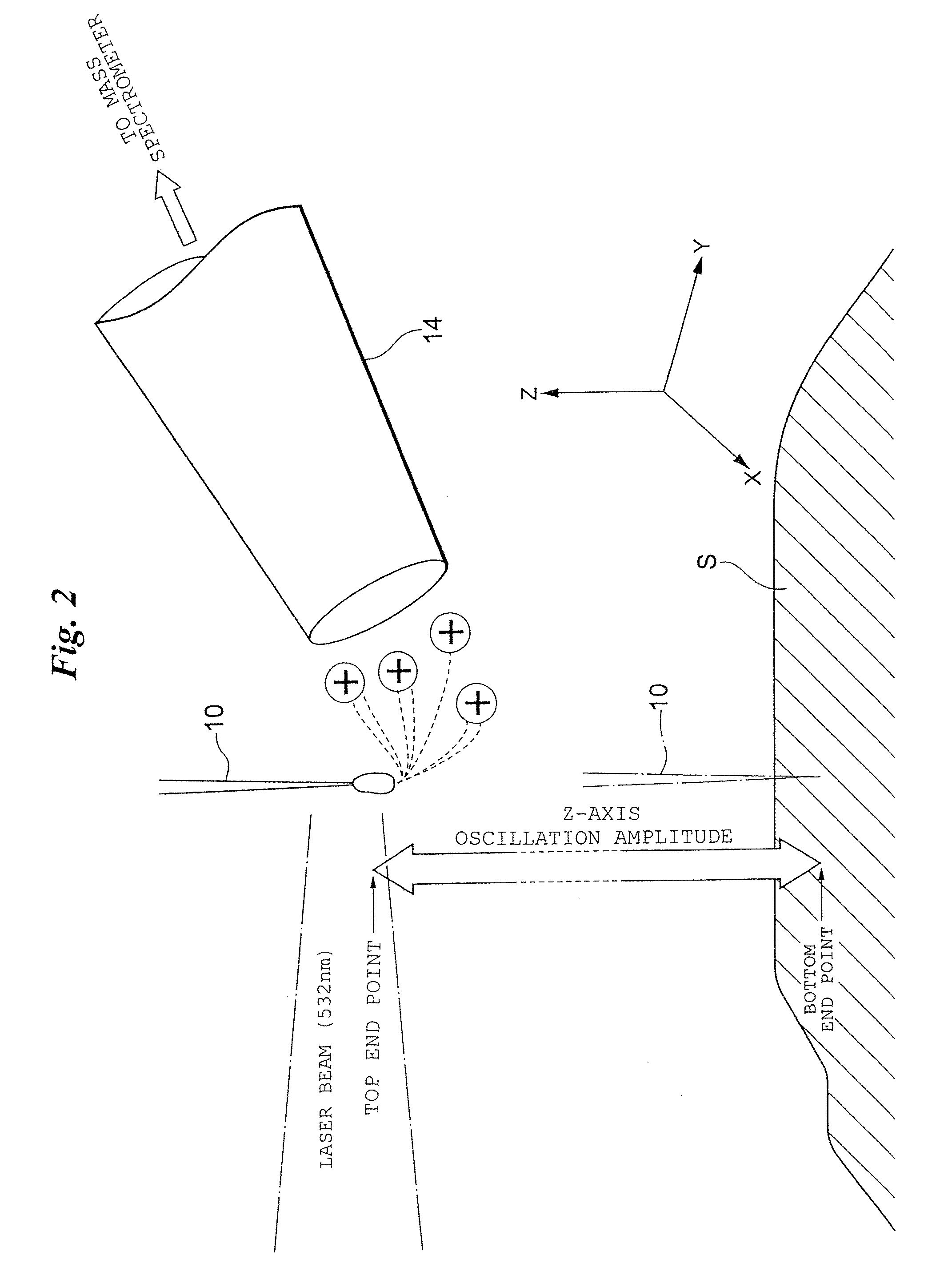
[0083]The metal probe 10 is driven in oscillatory fashion between the position of a miniscule droplet produced at the tip of the capillary 30 (the sample capture position, bottom dead center, bottom end point or lower-limit position) and a position spaced slightly ...

third embodiment

[0118]The characterizing feature of the third embodiment includes placing a side electrospray apparatus 50 at a position diagonally below the origin position (top end point) of the probe and spraying a charged droplet (from diagonally downward position) from the electrospray apparatus (preferably a nanoelectrospray) 50 toward a trace amount of sample, which has been captured at the tip of the probe 10 located at the top end point, thereby dissolving and spraying the sample and blowing it through the ion-sampling capillary 14 so that it is introduced into the mass spectrometry apparatus. If the electrospray solvent is one such as water, ethanol, methanol or other electrolyte, any of these can be used.

[0119]The electrospray apparatus (nanoelectrospray apparatus) 50 includes a very slender metal capillary 51 supplied with solvent, and an external cylinder 52 provided outside the capillary with a clearance therebetween. A high voltage is applied to the capillary 51.

[0120]It may be so ar...


PUM


Abstract

A biological sample can be subjected to measurement, description and ionization of ions is possible under atmospheric pressure without undergoing pretreatment. Imaging having a resolution on the nanometer order can be performed. An STM needle (probe) of an XYZ-axis-drive piezoelectric element is oscillated along the Z axis to contact the sample to a depth on the nanometer order and capture molecules at the needle tip. A pulsed high voltage is applied to the needle, achieving needle electrospray. The sample molecules are then desorbed and ionized, and mass spectrometry is carried out. The needle is swept in the XY directions, oscillation is repeated and an image obtained by molecular imaging of a nanometer area of the biological sample is measured. The probe may be brought into contact with a droplet produced at the tip of a capillary connected to the outlet port of a liquid chromatograph to capture a sample.

Description

CROSS-REFERENCE TO RELATED ED APPLICATIONS[0001]This application is a continuation-in-part of International Application No. PCT / JP2007 / 059438, filed Apr. 26, 2007, which claims priority from Japanese Application No. 2006-125398, filed Apr. 28, 2006, and Japanese Application No. 2006-135205, filed May 15, 2006, the entire disclosures of each of which are incorporated by reference herein.BACKGROUND OF THE INVENTION[0002]1. Field of the Invention[0003]This invention relates generally to an ionization method and apparatus using electrospray. By way of example, the invention relates to an ionization method and apparatus using electrospray in which imaging is possible, and in another example, to an ionization method and apparatus using electrospray in which microfabrication is possible.[0004]2. Description of the Related Art[0005]Broadly speaking, there are two categories of imaging mass spectrometry for dealing with biological samples and industrial products. The first is matrix-assisted...

Claims


Application Information

Patent Timeline
Patent Type & Authority Patents(United States)
IPC IPC(8): B01D59/44
CPCB82Y35/00G01N27/62G01N30/7266H01J49/165G01Q60/16H01J49/0004H01J49/161G01Q30/02G01N2001/028G01N27/623
Inventor HIRAOKA, KENZOTAKAMIZAWA, ATSUSHI
Owner UNIVERSITY OF YAMANASHI
Why Eureka
Try Eureka