
Implantable power sources and sensors

a technology of applied in the field of implantable power sources and sensors, can solve problems such as the number of microorganisms

Inactive Publication Date: 2011-05-31
GLUSENSE LTD
View PDF97 Cites 20 Cited by
  • Summary
  • Abstract
  • Description
  • Claims
  • Application Information

AI Technical Summary

Benefits of technology

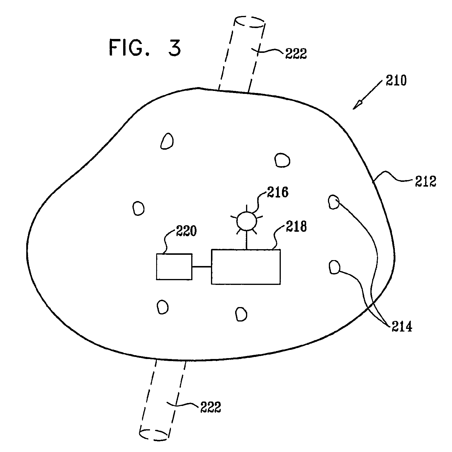
[0074]Typically, the membrane is adapted to allow the passage of nutrients, such as glucose, and other small molecules through the membrane, while inhibiting the passage of immune systems cells through the membrane. Examples of suitable membrane materials include polysulfone and polyurethane, among others. Isolation of the microorganisms from the immune system of the patient prevents the immune system from destroying the microorganisms and also reduces the tendency of the microorganisms to trigger an immune response.
[0078]Measurable responses typically comprise physiological responses of the microorganisms to levels of the specific compound. For example, increased glucose levels typically lead to increased glycolysis activity by the microorganisms, which results in increased energy release by the microorganisms and a temperature increase in the device. Thus, temperature within the device is used in some embodiments to indicate glucose levels. Additionally, optical changes induced by the response of the microorganisms to glucose levels facilitates the measurement of blood glucose levels, in some embodiments of the invention. For example, the scattering or absorption of light due to the microorganisms or the medium within which the cells reside typically changes in response to varying glucose levels. In addition, spectroscopy techniques provide quantification of glucose changes, as well as the quantification of other blood components such as hemoglobin or hematocrit, for the detection of patient anemia.

Problems solved by technology

Additionally, the semi-permeable barrier provides a physical barrier limiting the number of microorganisms in the device due to the limited space inside the semi-permeable barrier.

Method used


Image

  • Implantable power sources and sensors
  • Implantable power sources and sensors

Examples


Embodiment Construction

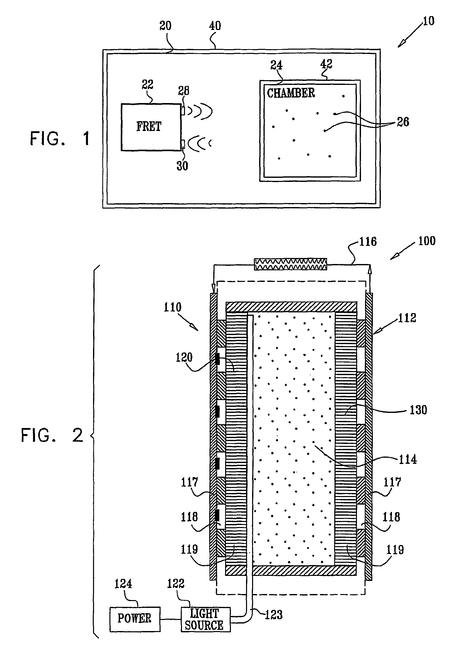
[0151]FIG. 1 is a schematic illustration of an implantable device 10 for detecting a concentration of a substance in a subject, such as a blood constituent or other body fluid constituent of the subject, in accordance with an embodiment of the present invention. Device 10 comprises an implantable housing 20 that holds a fluorescence resonance energy transfer (FRET) measurement device 22 and cells 26. FRET measurement device 22 comprises a light source 28, such as a laser, and a FRET detector 30. Cells 26 are genetically engineered to produce, in situ, a FRET protein having a FRET complex comprising a fluorescent protein donor, a fluorescent protein acceptor, and a binding site for the substance. The FRET complex is configured such that binding of the substance to the binding site changes the configuration of the complex, and thus the distance between the donor and the acceptor. FRET detector 30 detects this change in distance to determine the quantity of the FRET complex in each of ...


PUM

PropertyMeasurementUnit
molecular weightaaaaaaaaaa
concentrationaaaaaaaaaa
distanceaaaaaaaaaa

Abstract

A protein is provided, including a glucose binding site, cyan fluorescent protein (CFP), and yellow fluorescent protein (YFP). The protein is configured such that binding of glucose to the glucose binding site causes a reduction in a distance between the CFP and the YFP. Substance monitoring apparatus (210) is also provided, including a semi-permeable barrier (212), adapted to be implanted in a body of a subject and to allow passage therethrough of a substance, while inhibiting passage therethrough of immune cells; and microorganisms (214), disposed within the semi-permeable barrier (212) so as to produce a measurable response to a level of the substance. A sensor (220) is adapted to measure the measurable response and not to measure a response of any mammalian cells that may be disposed within the semi-permeable barrier (212).

Description

CROSS-REFERENCES TO RELATED APPLICATIONS[0001]This application is a §371 national stage of PCT International Application No. PCT / IL2005 / 000743, filed Jul. 13, 2005, and claims the benefit of U.S. Provisional Applications Nos. 60 / 658,716, filed Mar. 3, 2005; and 60 / 588,211, filed Jul. 14, 2004, the contents of all of which are hereby incorporated by reference into this application.REFERENCE TO SEQUENCE LISTING[0002]This application incorporates-by-reference nucleotide and / or amino acid sequences which are present in the file named “110418—0518—77411_Substitute_Sequence_Listing_GC.txt,” which is 24.2 kilobytes in size, and which was created Apr. 18, 2011 in the IBM-PC machine format, having an operating system compatibility with MS-Windows, which is contained in the text file filed Apr. 18, 2011 as part of this application.FIELD OF THE INVENTION[0003]The present invention relates generally to implantable power sources and sensors, and specifically to implantable bio-fuel cells and met...

Claims


Application Information

Patent Timeline
Patent Type & Authority Patents(United States)
IPC IPC(8): A61B5/00C12N15/85C07H21/04C07K14/00
CPCA61B5/14532A61K49/0045A61K49/0047G01N33/54373C07K14/43595A61K49/0056C07K2319/60
Inventor GROSS, YOSSIWILLIGER, BEN-TSIONHYMAN, TEHILANEUFELD, TOVA
Owner GLUSENSE LTD
Learn More