Method and apparatus for controlling power factor correction

a power factor and control method technology, applied in the direction of electric variable regulation, process and machine control, instruments, etc., can solve the problems of increasing power loss through transmission lines, noise in power lines, and large size of inductor in full cycle, so as to reduce noise, small ripple current, and low harmonic distortion

Active Publication Date: 2011-08-02
MARVELL ASIA PTE LTD
View PDF24 Cites 54 Cited by
  • Summary
  • Abstract
  • Description
  • Claims
  • Application Information

AI Technical Summary

Benefits of technology

[0023]In view of the foregoing, it is an object of the present invention to provide a power factor correction controller, which dynamically changes operation mode of a boost converter during a half cycle of the voltage, thus gaining the benefit of small size inductor, low harmonic distortion, and small ripple current. A digital signal processor calculates the duty cycle and frequenc

Problems solved by technology

If an electrical load is not purely resistive, it may introduce noise into the power line and may increase power losses through transmission lines.
However, at a given power level, if the continuous mode is used, the size of the inductor must be large in the full cycle.
When the critical mode is used, the size of the inductor can be small, but the ripple current is very high, thus requiring a large input filter.
Another disadvantage of conventional bo

Method used


Image

  • Method and apparatus for controlling power factor correction
  • Method and apparatus for controlling power factor correction
  • Method and apparatus for controlling power factor correction

Examples


Embodiment Construction

[0048]Objects and advantages of the present invention will become apparent from the following detailed description.

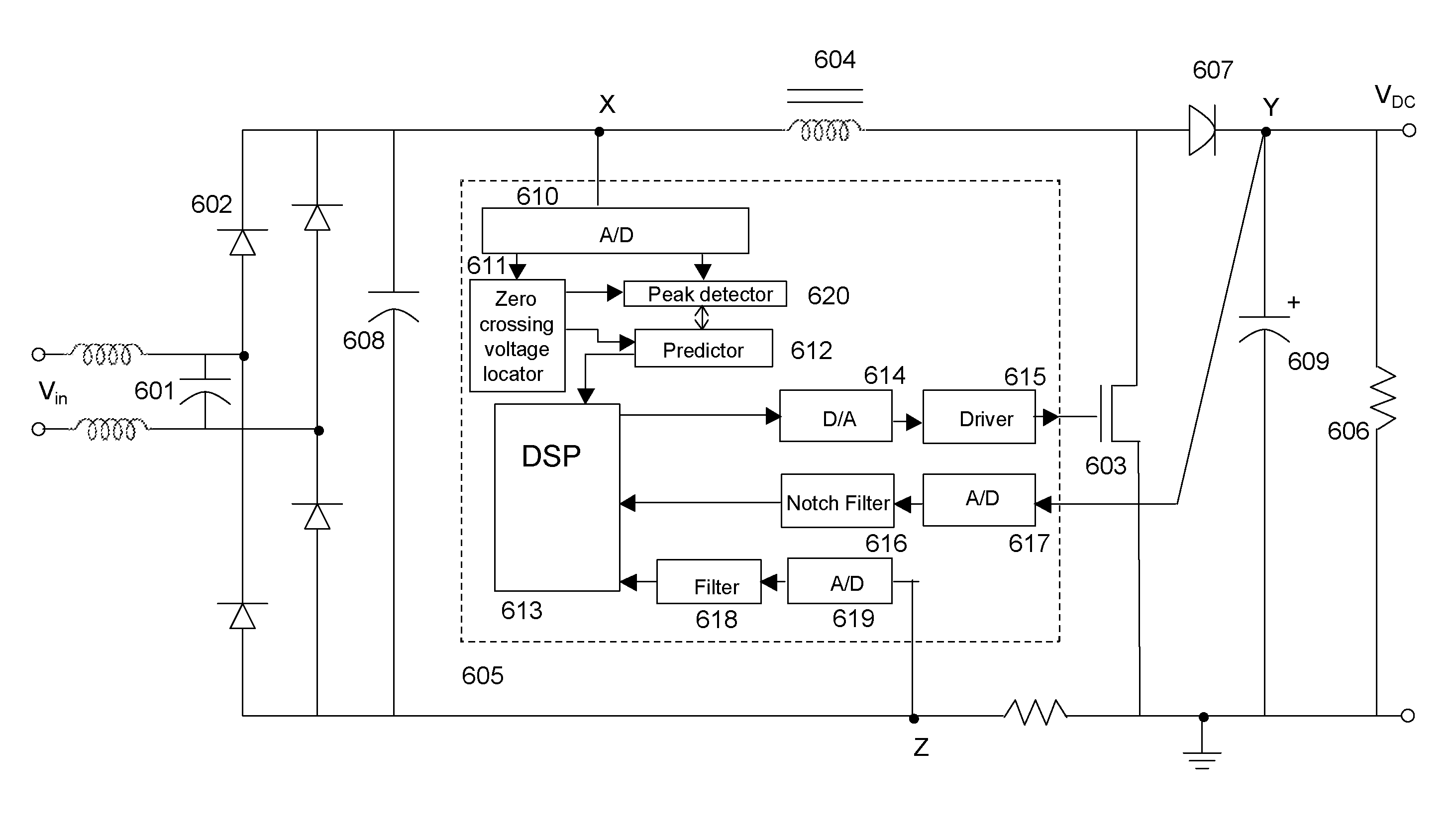
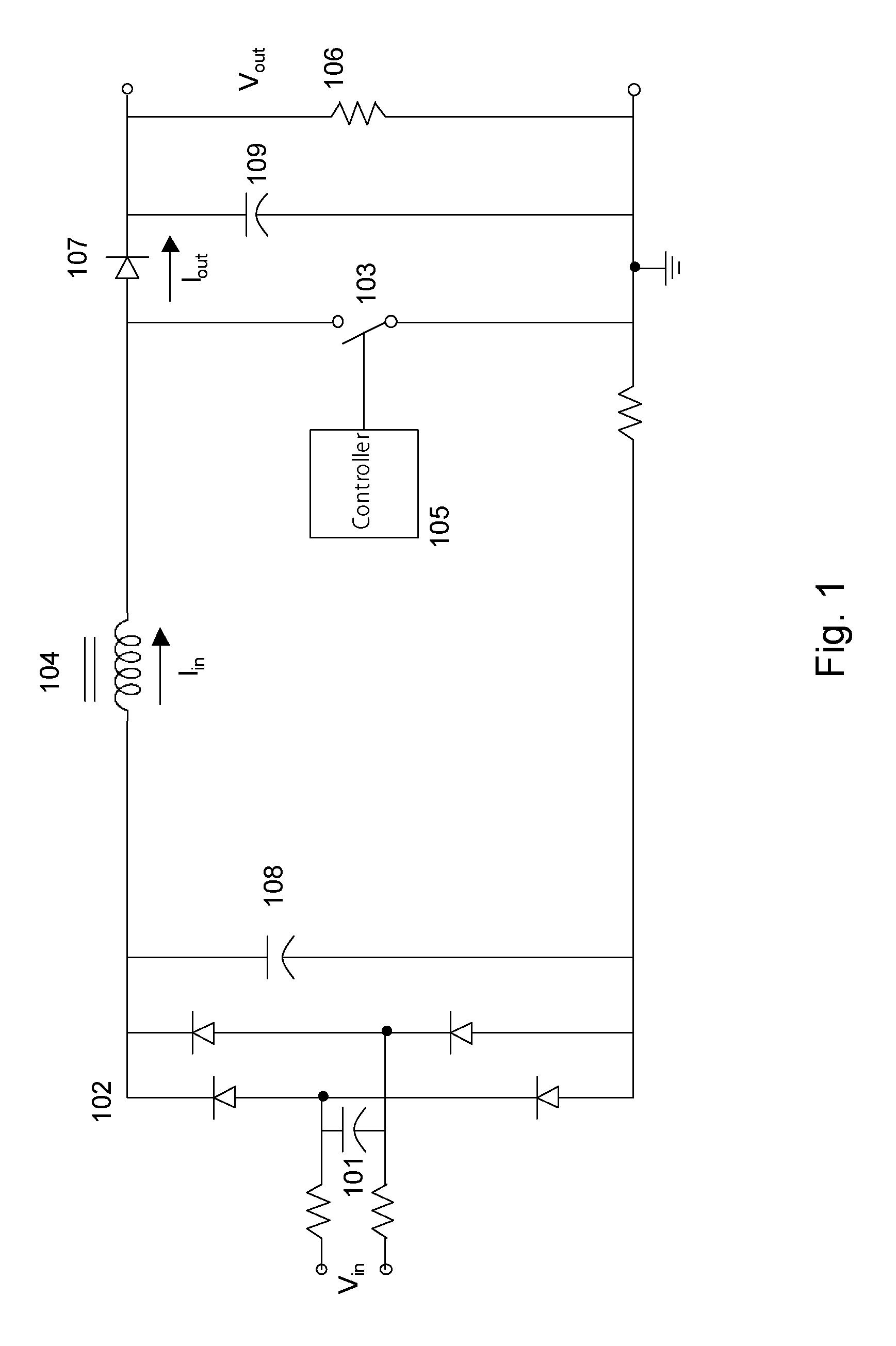
[0049]FIG. 6A shows a block diagram of an apparatus for power factor correction, employing a multiple mode controller according to one embodiment of the present invention. The controller 605 shown in FIG. 6A can dynamically switch the operation mode of the boost converter among continuous mode, critical mode, and discontinuous mode. The controller 605 is a DSP (Digital Signal Processor). In one embodiment, the controller 605 is an ASIC (Application Specific Integrated Circuit). Other embodiments for controller 605, including microprocessors and other hardware / software / firmware implementation will be apparent to ordinarily skilled artisans. Other parts of the boost converter shown in FIG. 6A are similar to those shown in FIG. 1.

[0050]As shown, the controller 605 obtains inputs at points X, Y, and Z. The controller 605 senses a zero crossing voltage at point X; senses a v...


PUM


Abstract

In a method and apparatus for controlling power factor correction (PFC) in mixed operation modes, a frequency of the input voltage is obtained by detecting the zero crossing points of the input voltage. A peak of the input voltage is obtained by detecting input voltage with 90 degree phase. Thus, the present invention predicts the input voltage by its frequency and peak and the characteristic of the sine wave. A digital signal processor computes the duty and frequency of a boost switch, switching the operation mode of the boost converter among continuous mode, critical mode and discontinuous mode according to input voltage or the load. According to another aspect, the operation is switched to critical mode from the average current mode when a zero current is detected before the charging and recharging cycle of the boost switch is finished. Overcurrent protection may be achieved by controlling current in response to detected voltage to provide a substantially constant power level. The overcurrent protection may be adaptive in nature. In this aspect, an adaptive driver for a PFC controller reduces the slew rate of signals over the boost switch of the PFC controller. The adaptive driver may have a group of transistors which may be divided into a plurality of branches. The charging current through the boost switch may be increased by turning on an increasing number of branches until the voltage over the switch exceeds a reference voltage, and this may determine the number of branches to drive the boost switch during normal operation.

Description

CROSS-REFERENCE TO RELATED APPLICATION[0001]This application claims the benefit of priority to previously filed U.S. provisional patent application Ser. No. 60 / 910,733, filed Apr. 9, 2007, entitled Adaptive Driver for Power Factor Correction (PFC) Controller. That provisional application is hereby incorporated by reference in its entirety.[0002]This application also is a continuation-in-part of U.S. application Ser. No. 11 / 849,158, filed Aug. 31, 2007, which is a continuation-in-part of U.S. application Ser. No. 10 / 804,660, filed Mar. 19, 2004, now U.S. Pat. No. 7,266,001. These also are incorporated by reference in their entirety.BACKGROUND OF THE INVENTION[0003]1. Field of the Invention[0004]The present invention relates to power factor correction (PFC), and more specifically to multiple mode power factor correction, and to drivers for PFC controllers.[0005]2. Description of Related Art[0006]An electrical load may appear to a power supply as a resistive impedance, a capacitive imp...

Claims


Application Information

Patent Timeline
IPC IPC(8): H02M7/04
CPCH02M1/4225Y02B70/126Y02B70/10
Inventor NOTOHAMIPRODJO, HUBERTUSLIN, JIANQINGZHANG, HONG LIANG
Owner MARVELL ASIA PTE LTD
Why Eureka
Try Eureka