[0008]As a result of the fact that the pipeline is formed with a foamed plastics material and / or with a dense plastics material, one outer face of the pipeline and / or one inner face of the pipeline comprising a wrapping with at least one linear reinforcing element for reinforcement, at least in certain sections, the pipeline according to the s invention has a low weight while having a high level of security against buckling, or
flexural strength, in all sections of the pipeline. Furthermore, the use of a foamed plastics material for forming the pipeline renders additional encasing of the pipeline with a suitable insulation material to reduce thermal losses dispensable as the foamed plastics material assumes the function of
thermal insulation in addition to the
air conduction function. When using the dense plastics material, for example in the form of a thin
plastic film or the like, there is, by contrast, no appreciable
thermal insulation capacity. The possibility of variation, in certain sections, of the mechanical loading capacity of the reinforcement by means of a change in the “winding density” of the wrapping means that the pipeline according to the invention can be optimally adjusted to different local loading requirements along the section for laying, resulting in a potentially considerable reduction in weight.
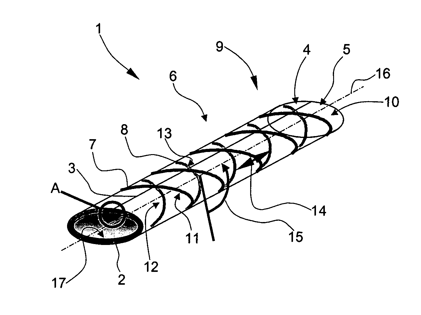
[0009]According to the invention, the wrapping for reinforcing the pipeline is formed with a plurality of
layers, the layers having a large number of windings wound in the same direction in each case. Wrapping the pipeline with a plurality of layers allows construction of a wrapping with relatively high mechanical strengths. Further, layers located one above the other comprise windings wound in opposite directions to form a net-like structure of the wrapping. As a result the wrapping is given an overall net-like structure which ensures a good bond between the individual layers wound onto the outer face of the pipeline. A spacing between the windings and / or an angle of slope between the windings and a pipeline longitudinal axis varies / vary in certain sections to change the winding density as a function of local
mechanical load requirements of the pipeline. Owing to the variation, in certain sections, in the spacing of the windings from each other and / or angles of slope or “winding density” of the wrapping, the mechanical loading capacity of the pipeline according to the invention may be optimally adjusted in certain sections to the respective requirements, resulting in a considerable reduction in weight. If, for example, the spacing of the windings from each other are reduced, the relevant section of the pipeline becomes more resistant to bending and thus more secure against buckling. This embodiment can be advantageous for example in sections for laying which require narrow pipeline radii of curvature. In contrast the reinforcement formed by the wrapping can turn out to be weaker in straight sections of the pipeline for laying, and this can be achieved by increasing the spacing of the windings from each other and / or increasing the angle of slope, i.e. overall by a reduction in the winding density. As a result the
flexural strength of the pipeline is definedly reduced, so as a consequence of the increased flexibility tolerance compensation and
assembly of the pipeline for example are facilitated. The reinforcement in straight sections of the pipeline for laying can optionally also be dispensed with entirely. The linear reinforcing elements for forming the windings are formed with at least one continuous
fiber which is enclosed by a matrix made of a thermosetting plastics material and / or a matrix made of a
thermoplastic polymer. This results in a reinforcement which is highly mechanically loadable yet lightweight and which can be simply applied, at least in certain sections, by wrapping the outer face of the pipeline and / or the inner face of the pipeline.
[0010]According to a further advantageous configuration of the pipeline according to the invention, to minimise flow losses, the inner face of the pipeline is constructed so as to be substantially smooth. This configuration ensures minimal flow resistance in the pipeline.
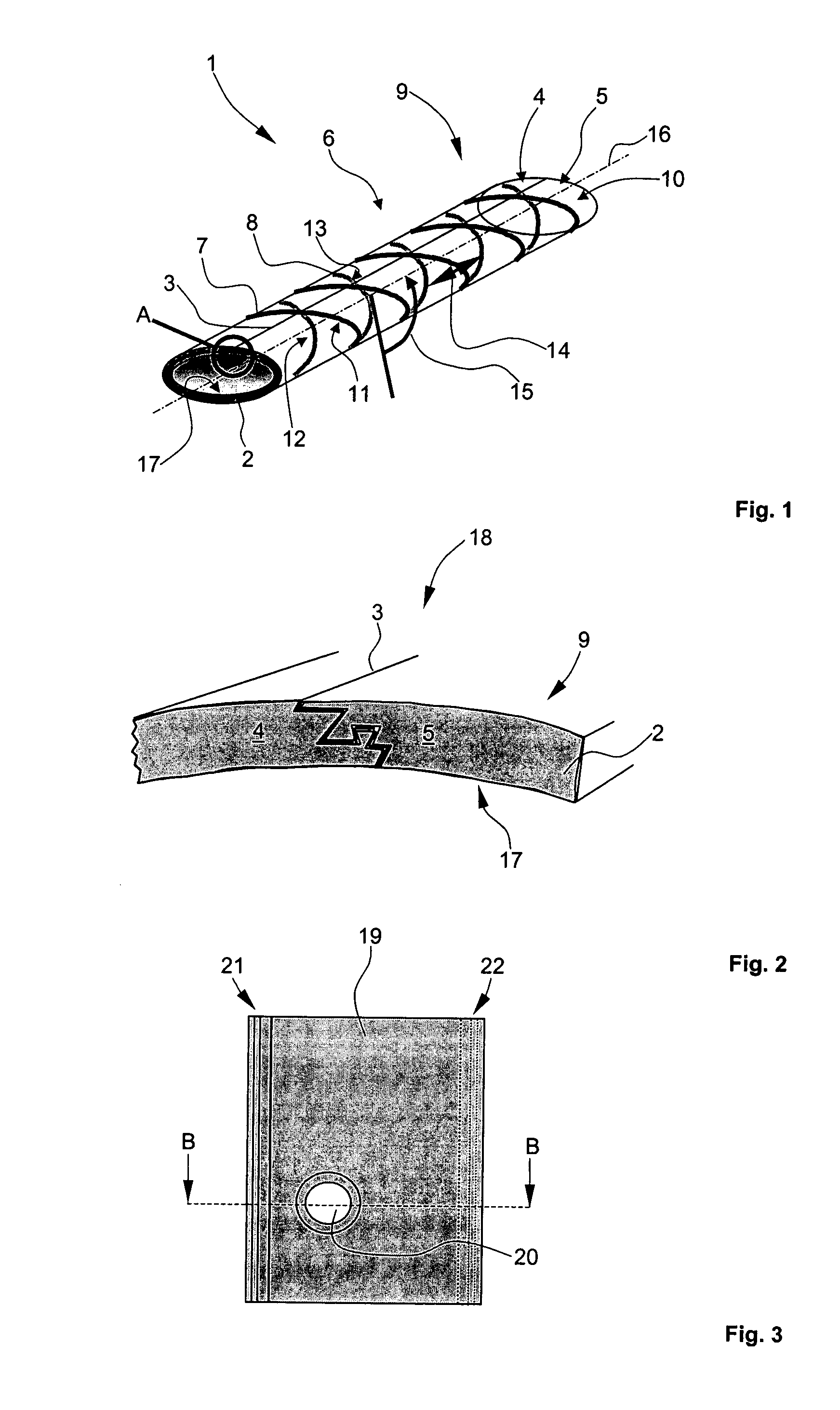
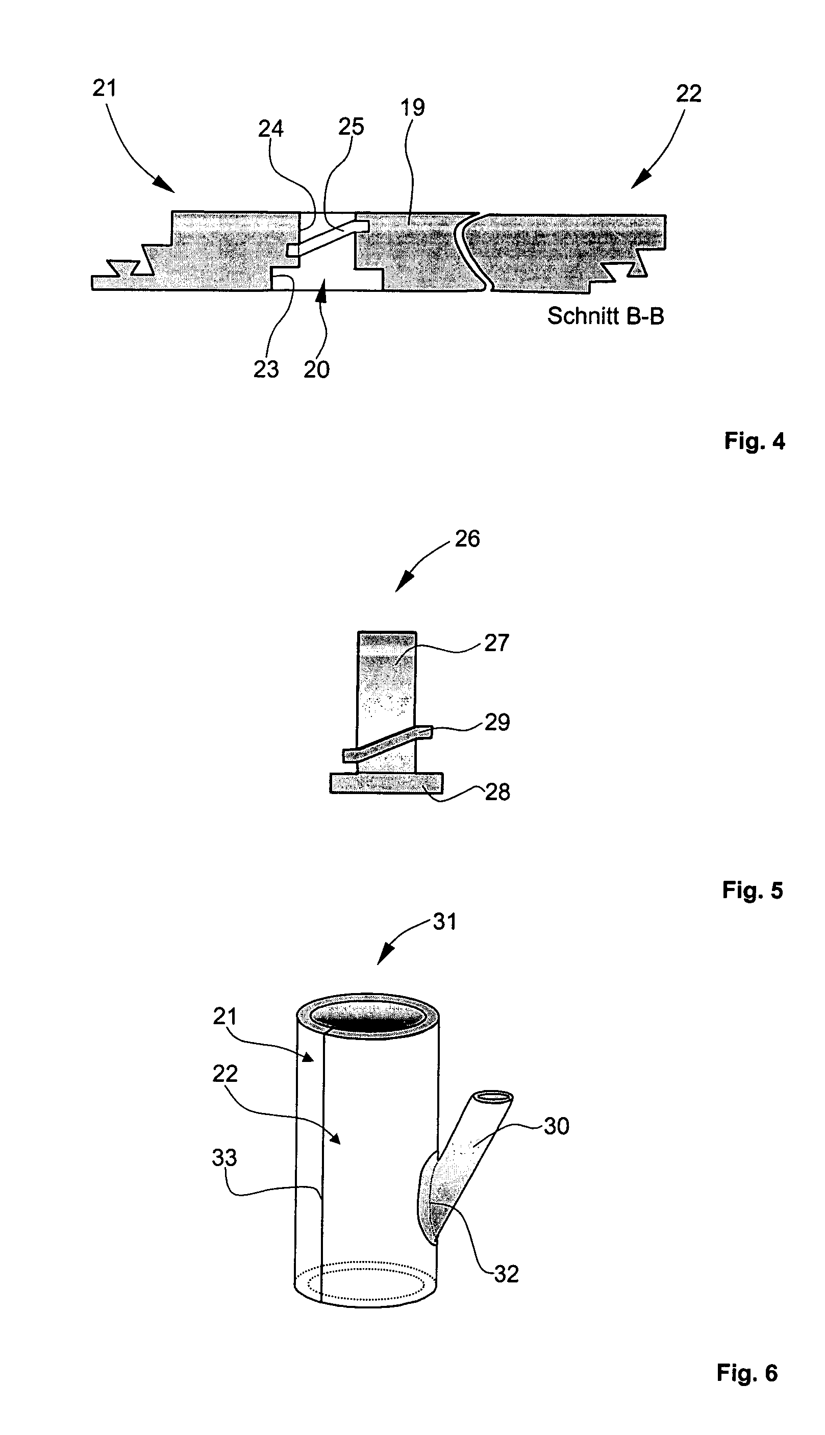
[0012]According to a further advantageous configuration in each case two of the mutually abutting longitudinal sides of the rolled-up portion or portions of material are constructed so they can be joined together by means of a connecting element in order to form the pipeline. The connecting element, which is preferably formed as a quick acting closure, allows quick and simple production of the pipeline by joining the longitudinal sides of the panel-like portion of material after rolling up. By introducing a
sealant into the connecting element virtually complete
air tightness of the pipeline may be produced along the thus formed longitudinal seam.
[0013]A further advantageous configuration provides that, for forming the pipeline, the respectively abutting longitudinal sides of the rolled-up portion or portions of material are constructed so they can be securely joined together, in particular can be glued or welded to each other. This results in a simpler pipeline construction which manages without an additional connecting element at the longitudinal sides of the portion of material.
[0015]According to a further advantageous configuration the inner face of the pipeline and / or the outer face of the pipeline comprise(s) an additional sealing layer to improve the
air tightness. Consequently any air losses owing to leaks in the region of the material wall of the pipeline are reduced, so overall only a very slight drop in pressure results along the pipeline.

