Device for two-dimensional imaging of scenes by microwave scanning

a two-dimensional imaging and microwave scanning technology, applied in the direction of measurement devices, instruments, antennas, etc., can solve the problems of mass inertia, inability to obtain inability to achieve a sufficient image size, etc., to achieve acceptable image quality, short time, and the effect of avoiding high processing and expenditur

Inactive Publication Date: 2011-08-30
DEUTSCHES ZENTRUM FUER LUFT & RAUMFAHRT EV
View PDF11 Cites 29 Cited by
  • Summary
  • Abstract
  • Description
  • Claims
  • Application Information

AI Technical Summary

Benefits of technology

[0016]It is an object of the invention to provide a device which, by means of active or passive microwave scanning, is capable of imaging large fields of view and thus scenes in a short time and with acceptable image quality, without the high processing expenditure and expenditure for coherence as required in SAR evaluation, while using a minimum number of components, with said components further being of a simple configuration, thus making it possible to keep the costs, the constructional expenditure and the weight as low as possible.

Problems solved by technology

With the fully mechanized systems known as of yet, it is not possible, for obtaining a sufficient image size, to reach high enough image rates (e.g. in the range of 1 Hz or better) with sufficient spatial resolution (e.g. an angular resolution of 0.5°) and sensitivity (e.g. 1 K).
Mostly, large antenna structures have to be mechanically moved at a fast speed, which will inevitably lead to mass inertia problems.
Consequently, basic limits of such methods will be reached quite early (e.g. angular resolution>1°, image rates1 K).
Further still, it has to be noted that present-day fully mechanized imaging systems, when used in the micro / millimeter wavelength range, are not capable to accomplish a high spatial resolution while simultaneously offering a high image rate and sufficient sensitivity.
In addition to the extra hardware expenditure, one will often have to tolerate restrictions in the size of the field of view and in sensitivity, as well as problems in scanning.
In addition to an increased power consumption, increased mass and difficulties in the dissipation of lost heat, it will often be required to process an immense data flow.
Further, the image reconstruction from the measurement data and the calibration of these systems will cause considerable expenditure because, due to the large number of subsystems, there is an increased complexity of possible error sources which, however, have to be corrected.
Also a failure of individual subsystems due to said complexity is not an uncommon occurrence.
In most cases, however, such systems do require a high technical expenditure with resultant high costs.
Here, apart from the difficulties outlined above with respect to fully electronic systems, additional problems may occur during the adaptation of the partial images.
Nonetheless, with high expenditure in spite of hybrid technology, there can still be reached a high imaging quality under the aspects of image rate, spatial resolution and sensitivity (e.g. 25 Hz and 0.2° and <2 K).
Thus, in the above context, it is to be stated that fully electronic imaging systems or hybrid systems with mechanical and electronic rotation of the directional diagram in the micrometer / millimeter wavelength range, although at least partially or approximately capable of effecting a high spatial resolution with simultaneous high image rate and sufficient sensitivity, will require, for this purpose, a high expenditure with regard to hardware, data pick-up and image processing.
Difficulties are encountered particularly in connection with the calibration and the error correction of the systems because a large number of partial systems have to be attuned to each other.
The increased hardware expenditure clearly finds its equivalent in an increase of costs and weight and in the occurrence of a massive power loss.
Further, in many system solutions, a fully polarimetric operation is difficult or complex or even impossible.
These systems, however, when compared to the classical millimeter wavelength range (≦300 GHz), suffer from the disadvantages of a smaller penetration depth, increased atmospheric damping, deteriorated noise figures and increased technological complexity of the receivers (e.g. cooling), with a resultant restriction of their range of applications.
Of particular disadvantage in this known imaging method are the considerable computational processing expenditure and the coherence expenditure, both of them being always required in an SAR evaluation.

Method used


Image

  • Device for two-dimensional imaging of scenes by microwave scanning
  • Device for two-dimensional imaging of scenes by microwave scanning
  • Device for two-dimensional imaging of scenes by microwave scanning

Examples


case 1

Check of Persons:

[0072]The following specifications are assumed for the system design:

[0073]

Central frequency:f0 = 90 GHz,System band width:B = 5 GHz,System noise temperature:Tsys = 800 K,Angular resolution in the E- and H-plane:ΔΘE = ΔΘH = ΔΘ = 0.5°,Distance of the focal plane (scene):R0 = 3 m,Size of scene, height × width:ΘH = 41°, ΘB = 20°,Overlapping factor:u = 0.1,Scanning factor:s = 0.5,Time required per image:Timage = 1 s.

[0074]The overlapping factor indicates the extent to which successive resolution cells shall overlap each other; thus, in case of u=0, there is no overlap at all; at u=1, the overlap would be 100%, and the antenna lobe would not move any further so that no imaging would be possible. At u=0.1, consequently, the overlap would be 10%.

[0075]The scanning factor indicates by how many resolution cells the antenna lobe is allowed to move on within the integration time. The integration time indicates how long the measuring signal is allowed to continue to be integrat...

case 2

Observation:

[0087]The following specifications are assumed for the system design:

[0088]

Central frequency:f0 = 1.42 GHzSystem band width:B = 20 MHzSystem noise temperature:Tsys = 600 KAngular resolution in the E- and H-plane:ΔΘE = 0.7°, ΔΘH = 1.0°Satellite height above the earth:R0 = 750 kmSize of scene (strip width):WB = 1500 kmOverlapping factor:u = 0.1Scanning factor:s = 0.5

[0089]It is provided that the angular resolution is smaller one direction than in the other so as to reduce the projection effect for the resolution cell on the surface of the earth. Thereby, a substantially circular resolution cell is generated, as often desired by data users.

[0090]The effect of the earth's curvature is neglected here, and a flat earth is assumed. In a more-detailed analysis, this aspect can be easily taken into consideration.

[0091]Only one desired strip width will be predetermined because the satellite is to pick up data in a continuous manner and the indication of an image length will thus b...


PUM


Abstract

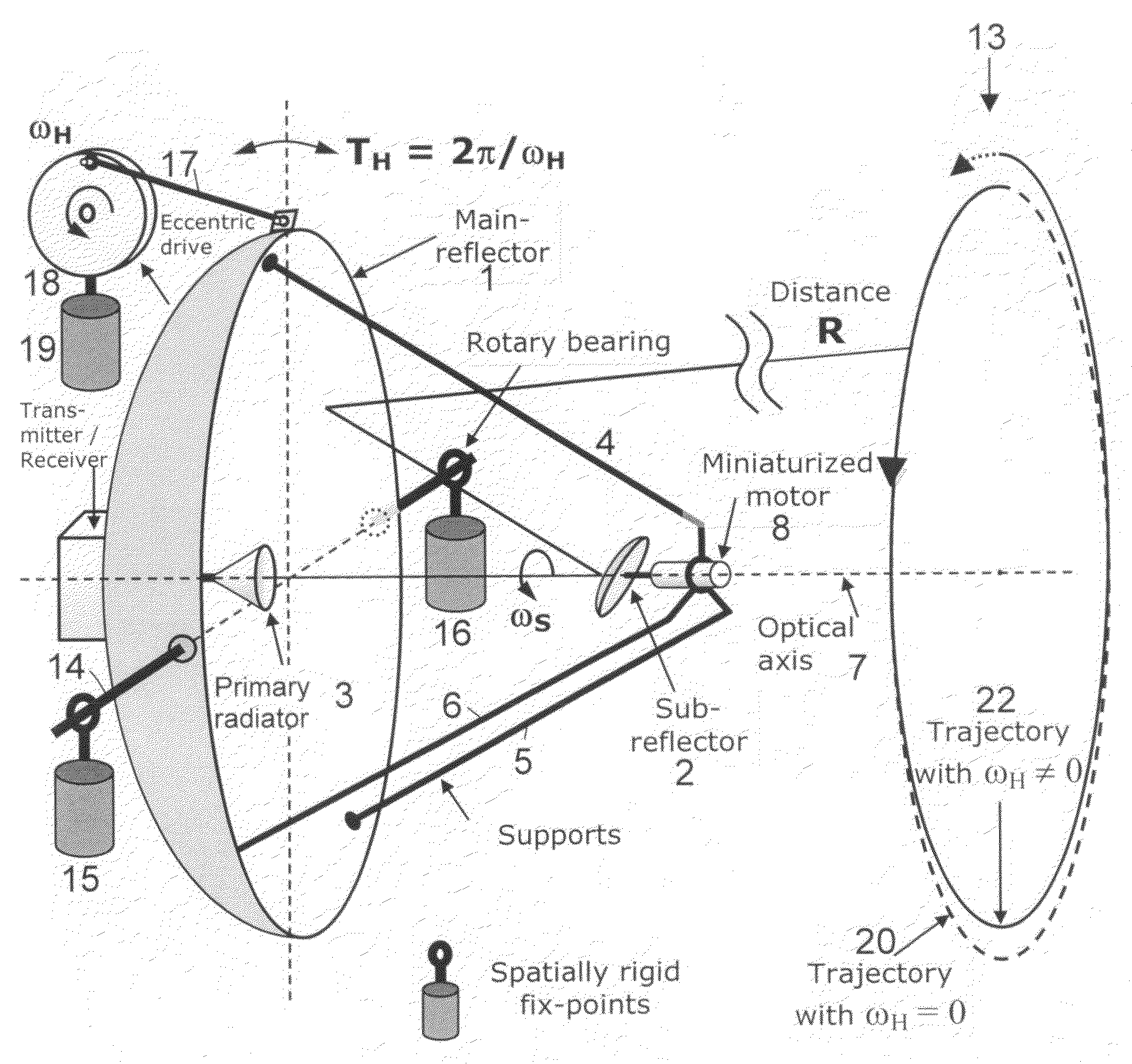
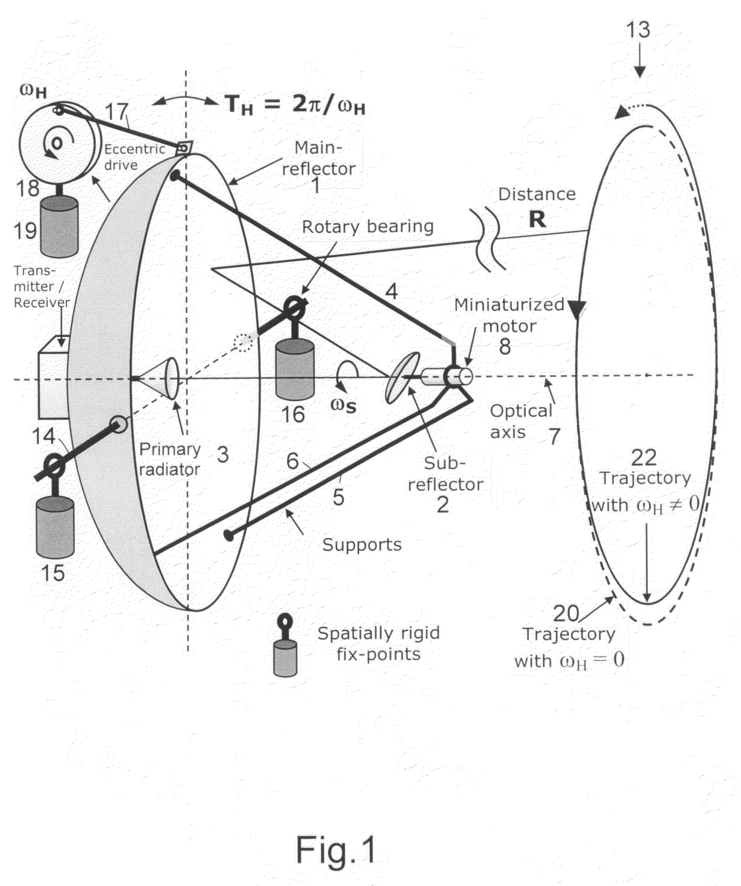
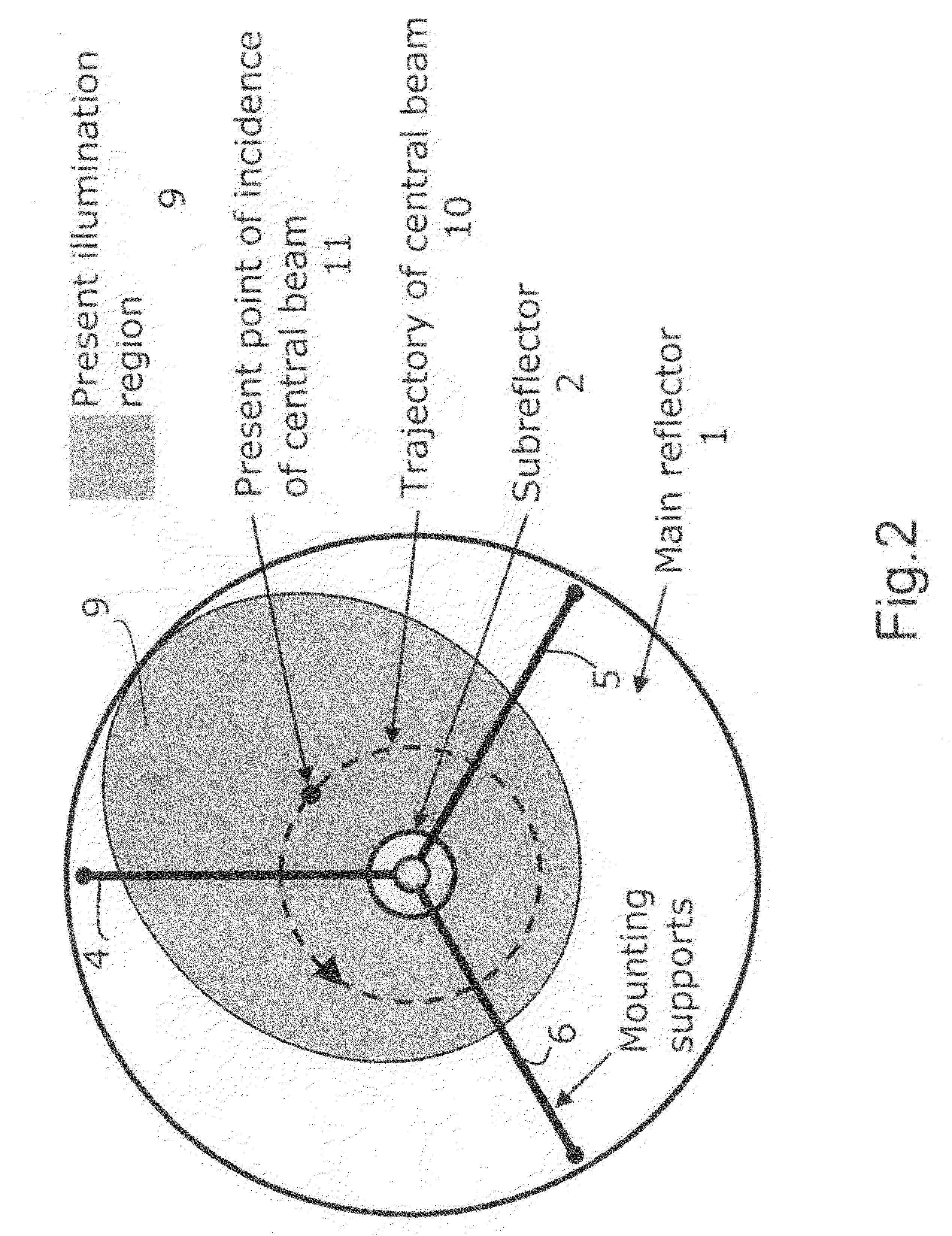
For two-dimensional imaging of scenes through continuous passive or active microwave scanning, use is made of a fully mechanized directional antenna array comprising a main reflector (1), a primary radiator array (3) and a subreflector (2) having a small size in comparison to the main reflector and being tilted relative to the optical axis (7) of the directional antenna array. First drive means (8) are operative to rotate the subreflector (2) about the optical axis (7), and second drive means (17,18) are operative to move the total directional antenna array in a direction approximately vertical to the optical axis (7). The moving speed of the subreflector (2) is very high in comparison to that of the total directional antenna array. The shape of the main reflector (1), the shape of the subreflector (2), the primary radiator (3), the distance between primary radiator and subreflector and the distance between subreflector and main reflector as focusing parameters are attuned to each other in such a manner that, for a given scene distance, an optimum focusing and an optimum size of the field of view are achieved. The focusing parameters and the moving speeds of the two drive means are set in a manner allowing for a gapless, continuous scanning of the scene with the aid of the focusing spot (12) moving at the scene distance. Applicability in remote investigation, particularly in earth observation and in safety technology.

Description

CROSS REFERENCE TO RELATED APPLICATIONS[0001]Applicant claims priority under 35 U.S.C. §119 of German Application No. 10 2008 013 066.4 filed on Mar. 6, 2008.FIELD OF THE INVENTION[0002]The invention relates to a device for two-dimensional imaging of scenes, e.g. of terrain, objects or persons, through continuous microwave scanning by use of a fully mechanized, movable reflector-type directional antenna array configured as a dual-reflector antenna, said directional antenna array comprising a rotationally symmetrical main reflector, a primary radiator assembly including one or a plurality of primary radiators and being arranged in the symmetry axis—coinciding with the optical axis of the directional antenna array—of the main reflector, and said directional antenna array further comprising a rotationally symmetrical subreflector having small dimensions relative to the main reflector, the symmetry axis of said subreflector being inclined relative to the optical axis of the directional ...

Claims


Application Information

Patent Timeline
Patent Type & Authority Patents(United States)
IPC IPC(8): H01Q3/12H01Q3/00H01Q19/10H01Q13/00
CPCG01S13/426G01S13/89H01Q3/10H01Q3/16H01Q3/20
Inventor PEICHL, MARKUSDILL, STEPHANJIROUSEK, MATTHIASBERTHEL, DOMINIK
Owner DEUTSCHES ZENTRUM FUER LUFT & RAUMFAHRT EV
Why Eureka
Try Eureka