Magnetic shielding for a PET detector system

a detector system and magnetic shielding technology, applied in the field of medical imaging arts, can solve the problems of minimal disturbance of patients, long lag time, and availability of both ct and spectroscopic imaging capabilities, and achieve the effect of improving workflow efficiency and efficient and effective retrofitting

Inactive Publication Date: 2011-09-06
KONINKLIJKE PHILIPS ELECTRONICS NV
View PDF17 Cites 25 Cited by
  • Summary
  • Abstract
  • Description
  • Claims
  • Application Information

AI Technical Summary

Benefits of technology

[0016]One advantage resides in improved workflow efficiency through integration of magnetic resonance imaging capability and PET or other second modality imaging capability into a single hybrid imaging system disposed in a single room.
[0017]Another advantage resides in enabling inclusion of a second modality imaging system proximate to a magnetic resonance scanner without introducing concomitant degradation of the magnetic resonance imaging.
[0018]Another advantage resides in enabling inclusion of a second modality imaging system proximate to a magnetic resonance scanner without introducing concomitant degradation of the second modality imaging.
[0019]Another advantage resides in enabling efficient and effective retrofitting of an existing magnetic resonance system enclosed in a radio frequency isolated room with a second modality imaging system.

Problems solved by technology

Separate imaging systems have a longer lag time between studies, and make it difficult to minimally disturb the patient between studies.
Thus, both CT and SPECT imaging capability are available with limited modifications to either the CT gantry or the spatially separated gamma camera.
However, construction of a hybrid imaging system including a magnetic resonance (MR) scanner and a second modality imaging system employing high energy particles or photons (such as SPECT or PET) is challenging.
Problematically, the electronics for radiation detectors used in PET scanners or other imaging systems that detect high energy particles or photons typically generate high levels of radio frequency interference.
Consequently, when considering placement in the same room with close proximity, there is an inherent practical incompatibility between a magnetic resonance scanner and an imaging system that detects high energy particles or photons.
Unfortunately, this approach vitiates many of the benefits of a hybrid MR / PET system.
The patient may find such a long-distance transfer uncomfortable, and shifting or other movement of the patient during such a long transfer can introduce spatial registration errors in images acquired by the MR and PET.
Moreover, difficulties can arise in transferring local coils used in magnetic resonance imaging across the long rail distance.
However, such low magnetic field regions, even in the case of an active-shield MR magnet, occur generally outside of the MR gantry at a relatively large radius near the midplane, thus requiring PMTs (photomultiplier tubes) to be relatively displaced from the PET detector material with a relatively long light guide path there-between; this approach reduces overall PET detector efficiency.
Also, this approach does not address the issue of radio frequency interference from the radiation detectors interfering with the magnetic resonance detection system.
Additionally, the integrated PET radiation detectors occupy valuable bore space in the MR scanner.
Still further, even with judicious positioning of the PET radiation detectors' PMT components at null points of the MR magnetic field, it can be expected that some stray magnetic fields from the MR system or from other sources may still cause problems for the PET imaging.
This approach reduces, but does not eliminate, MR bore space usage by PET components, and additionally introduces sensitivity issues in the PET system due to optical losses in the extensive fiber optical light coupling systems.
Moreover, while arranging the light detection electronics remotely is beneficial, some types of scintillation crystals exhibit spontaneous radioactivity that can still produce substantial radio frequency interference.
However, it remains the case that for whole-body applications, valuable bore space must be traded-off and / or a high level of complex and costly integration of PET components with MR gradient, radiofrequency transmit / receive body coil, and bore covers must be realized in this alternative.
A disadvantage of existing hybrid approaches is that these approaches are not conducive to retrofitting an existing magnetic resonance scanner.
The approach of Cho et al. requires availability of a PET scanner room suitably located adjacent to the radio frequency isolation room of the magnetic resonance scanner, and further requires cutting a passthrough into the separating wall and adding a complex and bulky railway system for coupling the PET and MR scanners located in separate rooms.
Approaches that integrate the PET radiation detectors into the MR scanner bore similarly add complexity to the retrofitting process, and may be unworkable with some existing MR scanners, particularly for whole-body applications.
The illustrative example of a hybrid PET / MR system is one in which stray magnetic fields are expected to be particularly problematic for the PET imaging.
However, PET imaging systems in other contexts can suffer from stray magnetic fields.
For example, other instruments that employ magnetic fields such as radiation generators for radiation therapy systems, electron microscopes, and so forth can produce problematic stray magnetic fields.
Indeed, even the earth's magnetic field can be a problematic stray magnetic field for sensitive PET imaging.

Method used


Image

  • Magnetic shielding for a PET detector system
  • Magnetic shielding for a PET detector system
  • Magnetic shielding for a PET detector system

Examples


Embodiment Construction

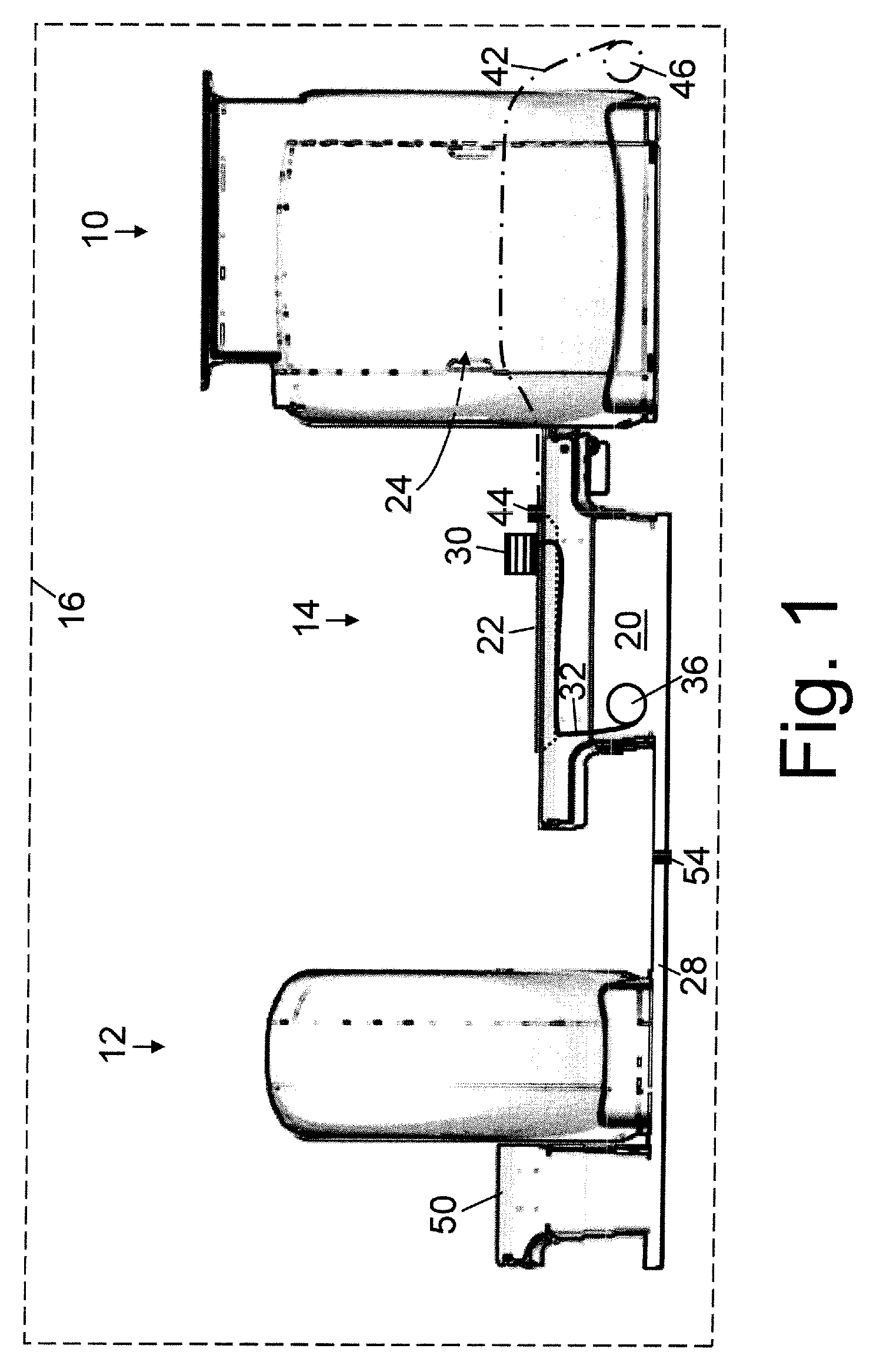
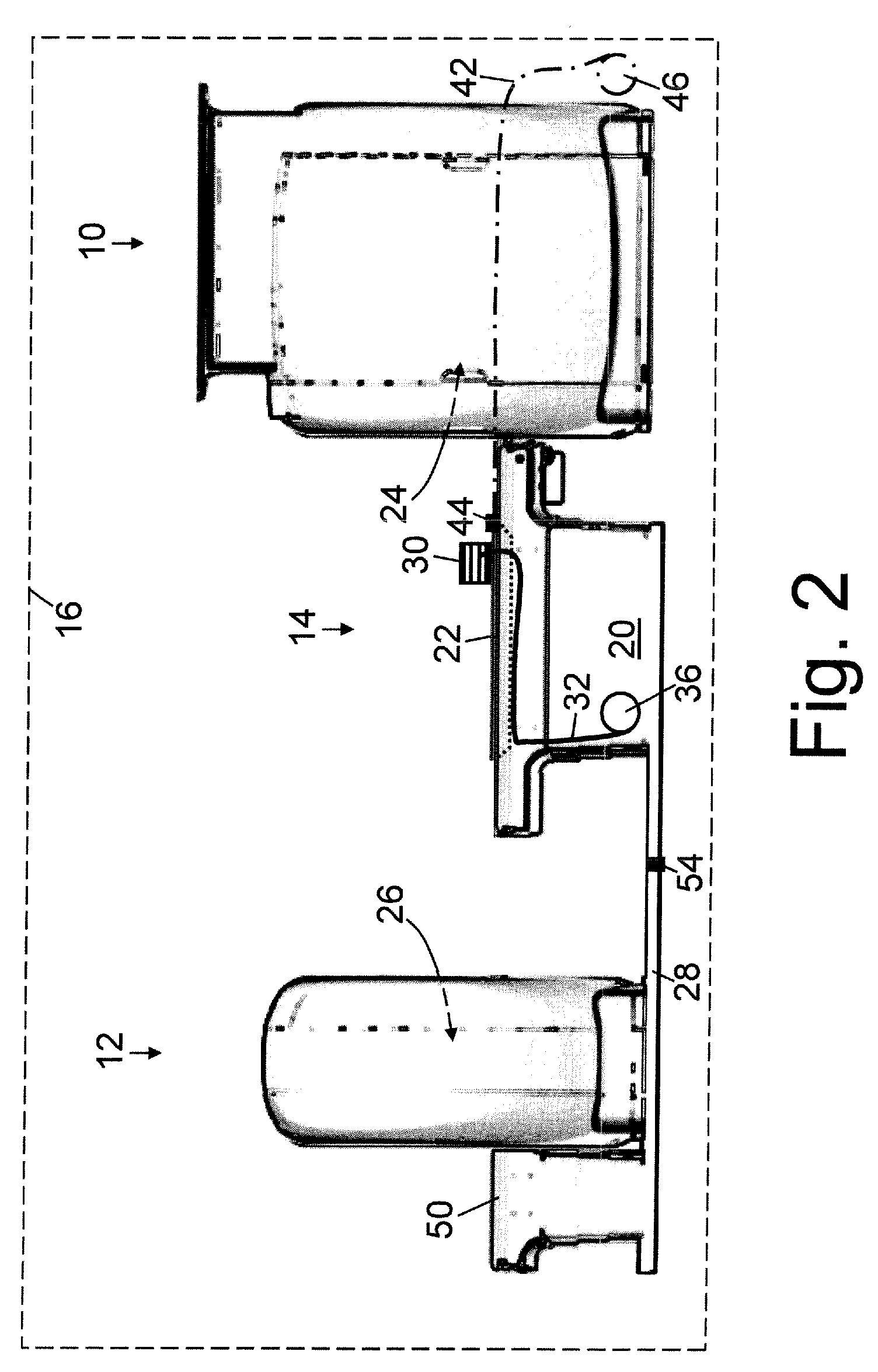
[0035]With reference to FIGS. 1-5, a hybrid imaging system includes a magnetic resonance scanner 10, a second modality imaging system 12, and a patient support, such as an illustrated patient bed 14, disposed between the magnetic resonance scanner 10, a second modality imaging system 12. A radio frequency shield substantially surrounds and defines a radio frequency isolated room or space 16. The magnetic resonance scanner 10, the second modality imaging system 12, and patient bed 14 are disposed within the radio frequency isolated room. The magnetic resonance scanner 10 in some embodiments is a commercial magnetic resonance scanner such as an Achieva or Intera magnetic resonance scanner available from Philips Medical Systems, Eindhoven, The Netherlands. More generally, the magnetic resonance scanner 10 can be substantially any type of scanner, such as the depicted horizontal cylindrical bore magnet scanner, an open bore scanner such as the Panorama magnetic resonance scanner availab...


PUM


Abstract

A positron emission tomography (PET) detector ring comprising: a radiation detector ring comprising scintillators (74) viewed by photomultiplier tubes (72); and a magnetic field shielding enclosure (83, 84) surrounding sides and a back side of the annular radiation detector ring so as to shield the photomultiplier tubes of the radiation detector ring. Secondary magnetic field shielding (76′) may also be provided, comprising a ferromagnetic material having higher magnetic permeability and lower magnetic saturation characteristics as compared with the magnetic field shielding enclosure, the second magnetic field shielding also arranged to shield the photomultiplier tubes of the radiation detector ring. The secondary magnetic field shielding may comprise a mu-metal. The PET detector ring may be part of a hybrid imaging system also including a magnetic resonance (MR) scanner, the PET detector ring being arranged respective to the MR scanner such that a stray magnetic field from the MR scanner impinges on the PET detector ring.

Description

CROSS REFERENCE TO RELATED APPLICATIONS[0001]This application is a continuation-in-part of U.S. Ser. No. 12 / 195,637 filed Aug. 21, 2008 which is a continuation of PCT application number PCT / US2007 / 081457 filed Oct. 16, 2007 which claims the benefit of U.S. provisional application Ser. No. 60 / 863,634 filed Oct. 31, 2006. U.S. Ser. No. 12 / 195,637 filed Aug. 21, 2008 is incorporated herein by reference in its entirety. PCT application number PCT / US2007 / 081457 filed Oct. 16, 2007 is incorporated herein by reference in its entirety. U.S. provisional application Ser. No. 60 / 863,634 filed Oct. 31, 2006 is incorporated herein by reference in its entirety.BACKGROUND OF THE INVENTION[0002]The present application relates to the medical imaging arts. It particularly relates to combined magnetic resonance (MR) and positron emission tomography (PET) imaging systems, and is described with particular reference thereto. The following relates more generally to imaging systems that combine the MR imag...

Claims


Application Information

Patent Timeline
Patent Type & Authority Patents(United States)
IPC IPC(8): G01V3/00
CPCG01R33/28G01R33/3875G01R33/421G01R33/422G01R33/481G01R33/4812G01T1/1603
Inventor DEMEESTER, GORDON D.MORICH, MICHAEL A.MCMAHON, KEVIN C.GRIESMER, JEROME J.
Owner KONINKLIJKE PHILIPS ELECTRONICS NV
Why Eureka
Try Eureka