
Method of forming a metal powder film a thermal conduction member, power module, vehicle inverter, and vehicle formed thereof

a metal powder and thermal conduction technology, applied in the field of metal powder, can solve the problems of increasing the cost of film forming facilities and the cost of compressed gas for use, low adhesion efficiency, and difficulty in forming a desired porous film having multi-functionality, etc., to achieve the effect of increasing the transformation of metal powder, enhancing adhesion efficiency, and low cos

Inactive Publication Date: 2011-09-27
TOYOTA JIDOSHA KK
View PDF7 Cites 2 Cited by
  • Summary
  • Abstract
  • Description
  • Claims
  • Application Information

AI Technical Summary

Benefits of technology

The present invention provides a method for improving the adhesion efficiency of metal powder when sprayed onto a substrate using a low-pressure compressed gas. By using a powder with a specific range of apparent density and average grain size, the adhesion efficiency is enhanced without the need for increased pressure or temperature of the metal powder. This allows for the formation of a porous film with poles uniformly dispersed therein on the surface of the substrate, which is effective in alleviating the difference in thermal expansion between members. The use of a powder with a lower apparent density or larger average grain size may decrease the adhesion efficiency, so it is important to select the appropriate range of apparent density and average grain size for optimal adhesion.

Problems solved by technology

However, in the case of forming the film by use of the metal powder by cold spraying, since the metal powder is sprayed in the solid-phase state, adhesion efficiency is low.
In this case, with increase in pressure of the compressed gas, cost of film forming facilities and cost of the compressed gas for use increase.
Further, the collision transformation of the metal powder at the time of collision becomes large, thereby making it difficult, for example, to form a desired porous film having multi-functionality (specifically a film in which poles having a desired size are uniformly dispersed).
However, in the case of raising the temperature of the metal powder to be collided with the substrate, the metal powder becomes more vulnerable to oxidation, and hence an inherent characteristic of cold spraying, that is to form a film containing a small amount of an oxide, may be impaired.
However, in the case of decreasing the grain size of the metal powder, the powder may be affected by repercussions of the compressed gas collided with and reflected on the substrate, and consequently, it is difficult to sufficiently increase the rate of the metal powder that is collided with the substrate.

Method used


Image

  • Method of forming a metal powder film a thermal conduction member, power module, vehicle inverter, and vehicle formed thereof
  • Method of forming a metal powder film a thermal conduction member, power module, vehicle inverter, and vehicle formed thereof
  • Method of forming a metal powder film a thermal conduction member, power module, vehicle inverter, and vehicle formed thereof

Examples


example 1

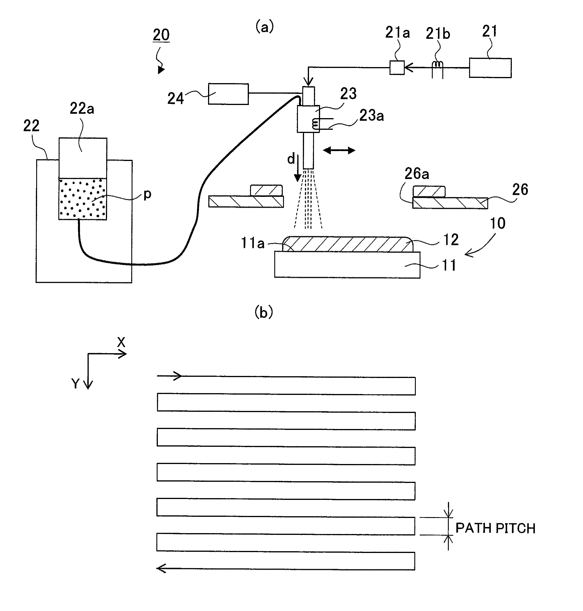
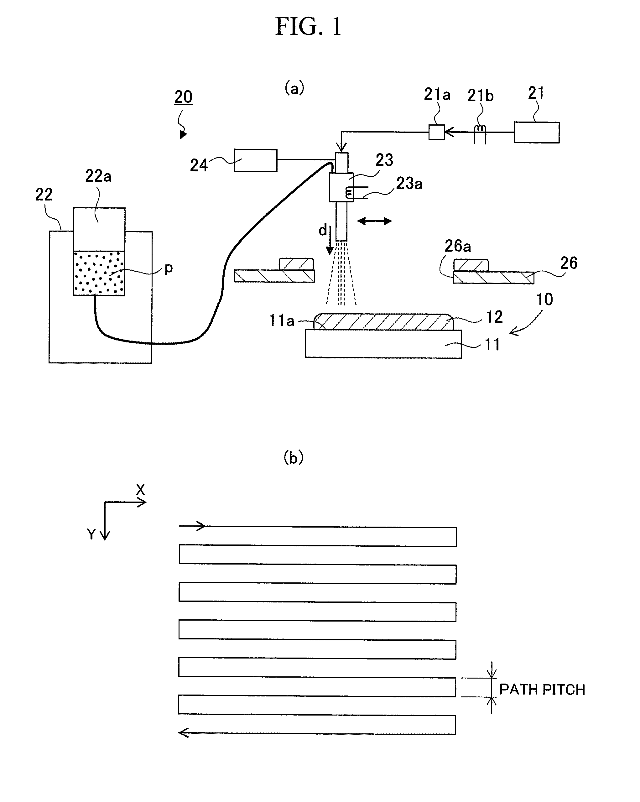
[0056]A thermal conduction member was produced where a copper film had been formed on a substrate by cold spraying. Specifically, the air (atmospheric air) is compressed such that a density of the copper film was 7.8 kg / m3 (holes: 12% by volume), and a metal powder made of copper, which was in a solid-phase state, was sprayed to the surface of a heat sink member (substrate) made of an aluminum alloy of 30×20 mm in size and 5 mm in thickness (HS standard: A6063S-T1), along with the compressed air (compressed gas), so that a film was formed using the copper powder, and a thermal conduction member was produced.

[0057]A more detailed description is given below: a nozzle for spraying was arranged in a position 30 mm from the top of the heat sink member where surface processing had been performed by shot-blasting, through a masking plate having an opening for masking of 30×20 mm in size. Next, as shown in a table of FIG. 4, a copper powder for film formation was granulated from a water-ato...

examples 2 to 5

[0058]In the same manner as in Example 1, a film of the copper powder was formed on the surface of the substrate. A different point from Example 1 is a powder used at the time of film formation. Specifically, as shown in FIG. 4, in Example 2, a powder was used having been granulated from a gas-atomized powder, milled by a nitrogen gas, made of copper and having a grain size of 3 μm, so as to have an average grain size of 18 μm and an apparent density of 1.88 g / cm3 as a copper powder for film formation. In Examples 3 and 4, powders were used having been sequentially granulated from an electrolytic powder, made of copper and having a grain size of 4.8 μm, so as to have average grain sizes of 22 μm and 21 μm and dummy densities of 1.64 g / cm3 and 1.5 g / cm3, as copper powders for film formation. Further, in Example 5, a dendritic powder having an average grain size of 19.3 μm and an apparent density of 1.64 g / cm3, shown in FIG. 5(a) was used as an electrolytic powder. The adhesion effici...

example 6

[0066]A thermal conduction member was produced in the same manner as in Example 1. A different point from Example 1 is that a film was formed on a temperature condition of the copper powder, immediately before collided with the substrate, of not lower than 50° C., shown in FIG. 8. A thermal conductivity of the film was then measured in the same manner as in Example 1. Results of the measurement are shown in FIG. 8.


PUM

PropertyMeasurementUnit
grain sizeaaaaaaaaaa
apparent densityaaaaaaaaaa
pressureaaaaaaaaaa

Abstract

There is provided a film forming method capable of enhancing adhesion efficiency of a metal powder by use of a low-pressure compressed gas even in the case of spraying the metal powder remaining in a solid-phase state to a substrate, to form a film, the method being a film forming method of spraying a metal powder p in a solid-phase state to a surface 11a of a substrate 11 along with a compressed gas, to form a film 12 of the metal powder p on the surface 11a of the substrate 11, wherein a powder, which at least contains a powder for film formation having an apparent density of 1.4 to 2.0 g / cm3 and an average grain size of not larger than 25 μm, is used as the metal powder p.

Description

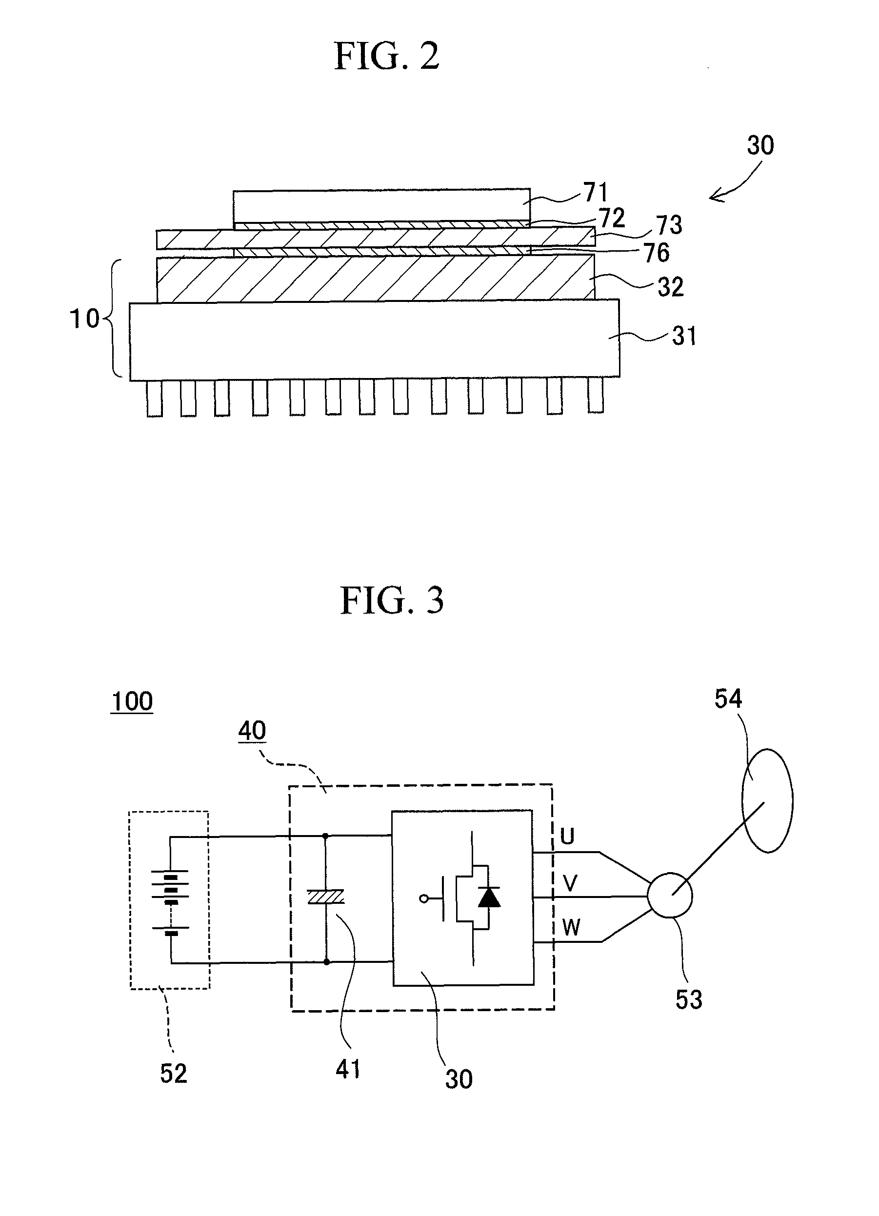
TECHNICAL FIELD[0001]The present invention relates to a film forming method of spraying a metal powder in a solid-phase state to the surface of a substrate along with a compressed gas to form a film containing a composition of the metal powder, a thermal conduction member where a film is formed by the film forming method, a power module comprising the thermal conduction member, a vehicle inverter comprising the power module, and a vehicle comprising the vehicle inverter.BACKGROUND ART[0002]A power module used in a vehicle inverter and the like has hitherto been constituted of electronic components shown in FIG. 9. Specifically, a power module 70 at least includes a power element 71 made of a silicon element, an insulating member 73 made of aluminum nitride to which the power element 71 is fixed through a solder layer 72, and a heat sink member 74 made of aluminum. Further, between the insulating member 73 and the heat sink member 74, a buffer member 75 made of copper-molybdenum (Cu—...

Claims


Application Information

Patent Timeline
Patent Type & Authority Patents(United States)
IPC IPC(8): B05D1/12
CPCC23C24/04H01L23/3735H01L21/4871H01L2224/32225Y10T428/249986H01L23/36H01L25/07
Inventor MIYAMATO, NORITAKATSUZUKI, YOSHIHIKO
Owner TOYOTA JIDOSHA KK
Learn More