Coherent optical receiver

a receiver and optical technology, applied in the field of coherent optical receivers, can solve the problem of difficulty in actual operation of analog/digital converters at a sampling frequency higher than a transmission speed, and achieve the effects of increasing the transmission speed of optical coherent communications, reducing the load imposed on digital processing, and increasing the transmission speed

Active Publication Date: 2011-10-11
NAT INST OF INFORMATION & COMM TECH
View PDF2 Cites 13 Cited by
  • Summary
  • Abstract
  • Description
  • Claims
  • Application Information

AI Technical Summary

Benefits of technology

An object of the present invention is to solve the above-described problems and to provide a coherent optical receiver which does not require optical PLL, whose clock can be synchronized with an optical phase modulated signal, and which can receive signals modulated in two optical modulation schemes; i.e., intensity modulation and modulation for coherent communications.
A coherent optical receiver according to the present invention comprises a 90-degree optical hybrid circuit which receives an optical-coherent-modulated signal light and local oscillation light, splits the received signal light to quadrature components I and Q, and outputs the quadrature components I and Q; I-channel and Q-channel photo detectors which respectively receive the quadrature components I and Q output from the 90-degree optical hybrid circuit; a clock extraction circuit which demodulates the received signal light so as to reproduce a clock whose speed is the same as that of the demodulated signal and which is synchronized therewith; I-channel and Q-channel sampling circuits which sample respective signals output from the I-channel and Q-channel photo detectors, at timings determined by the reproduced clock; and a digital signal processing section which digitally processes the sampled signals fed from the I-channel and Q-channel sampling circuits, converts the sampled signals to a digital signal, and outputs the digital signal. A phase offset signal detected by the digital signal processing section is fed back to the clock extraction circuit so as to control the phase of the clock. By use of filter functions realized by digital processing, the digital signal processing section compensates dispersion of light within a fiber and phase fluctuation during free-space propagation.
According to the present invention, clock extraction can be performed independently on the reception side, and the load imposed on digital processing decreases, whereby transmission speed can be increased. Further, extraction of a clock signal of the transmission speed is enabled through delay detection of light or through delaying and multiplication of signals produced by receiving light in a heterodyne scheme, and the sampling circuits are operated by the clock signal. Thus, the transmission speed of optical coherent communications can be increased.

Problems solved by technology

As described above, when optical coherent communications are realized by means of digital processing, operating analog / digital converters at a sampling frequency higher than a transmission speed is difficult in actuality, because of limitation on the operation speeds of the analog / digital converters.

Method used


Image

  • Coherent optical receiver
  • Coherent optical receiver
  • Coherent optical receiver

Examples


first embodiment

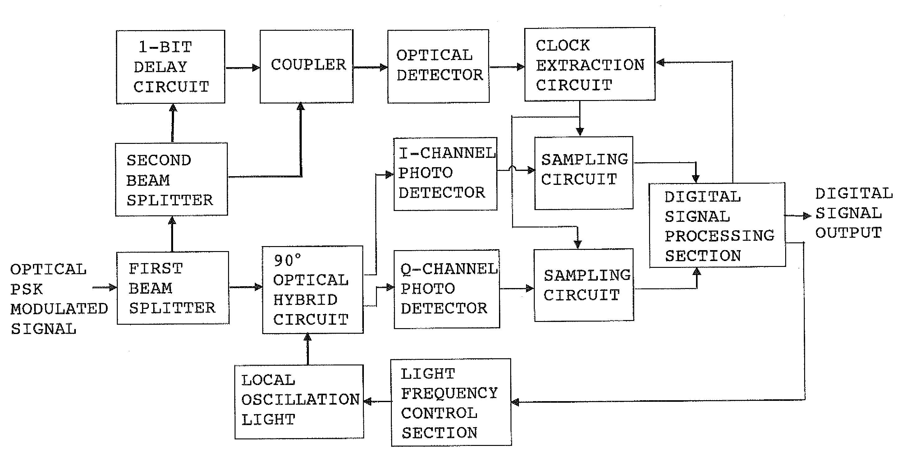
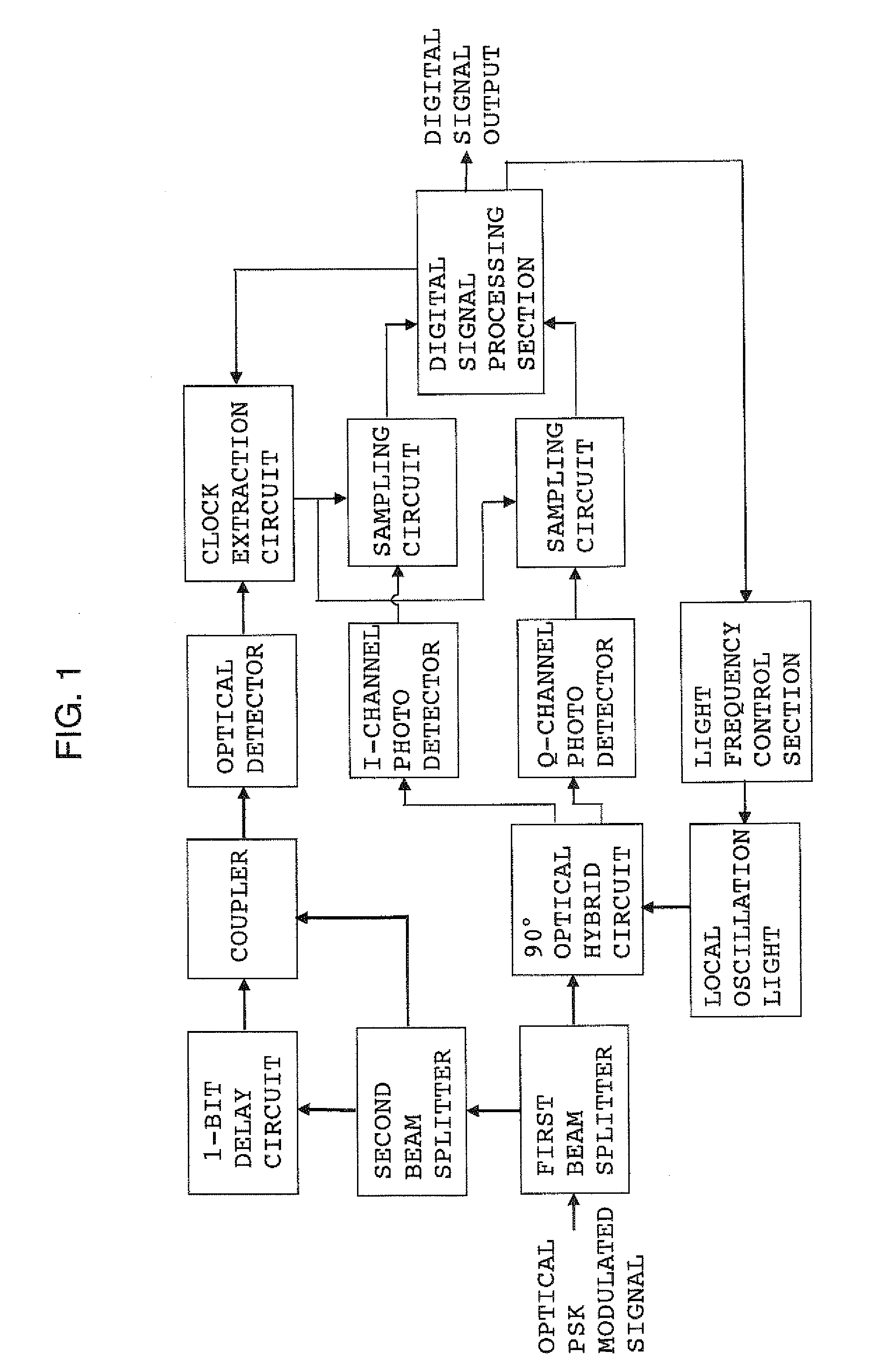
The present invention will now be described by way of examples. FIG. 1 is a circuit diagram of a coherent optical receiver showing the present invention. FIG. 1 shows an example in which extraction of a clock signal is performed at the optical signal level. An optical PSK (in particular, DPSK or BPSK) modulated signal (light beam) transmitted from a coherent optical transmitter (not shown) is split to two light beams by means of a first beam splitter. One light beam is led to a 90-degree optical hybrid circuit for splitting the input signal light to quadrature components I and Q. The other light beam is led to a second beam splitter. In the 90-degree optical hybrid circuit, the light beam is mixed with local oscillation light, and the resultant quadrature components I and Q are led to photo detectors for I and Q channels. The electric signal output from the photo detectors have a phase difference of 90° therebetween (SIN and COS waves), and carry pieces of information regarding the ...

second embodiment

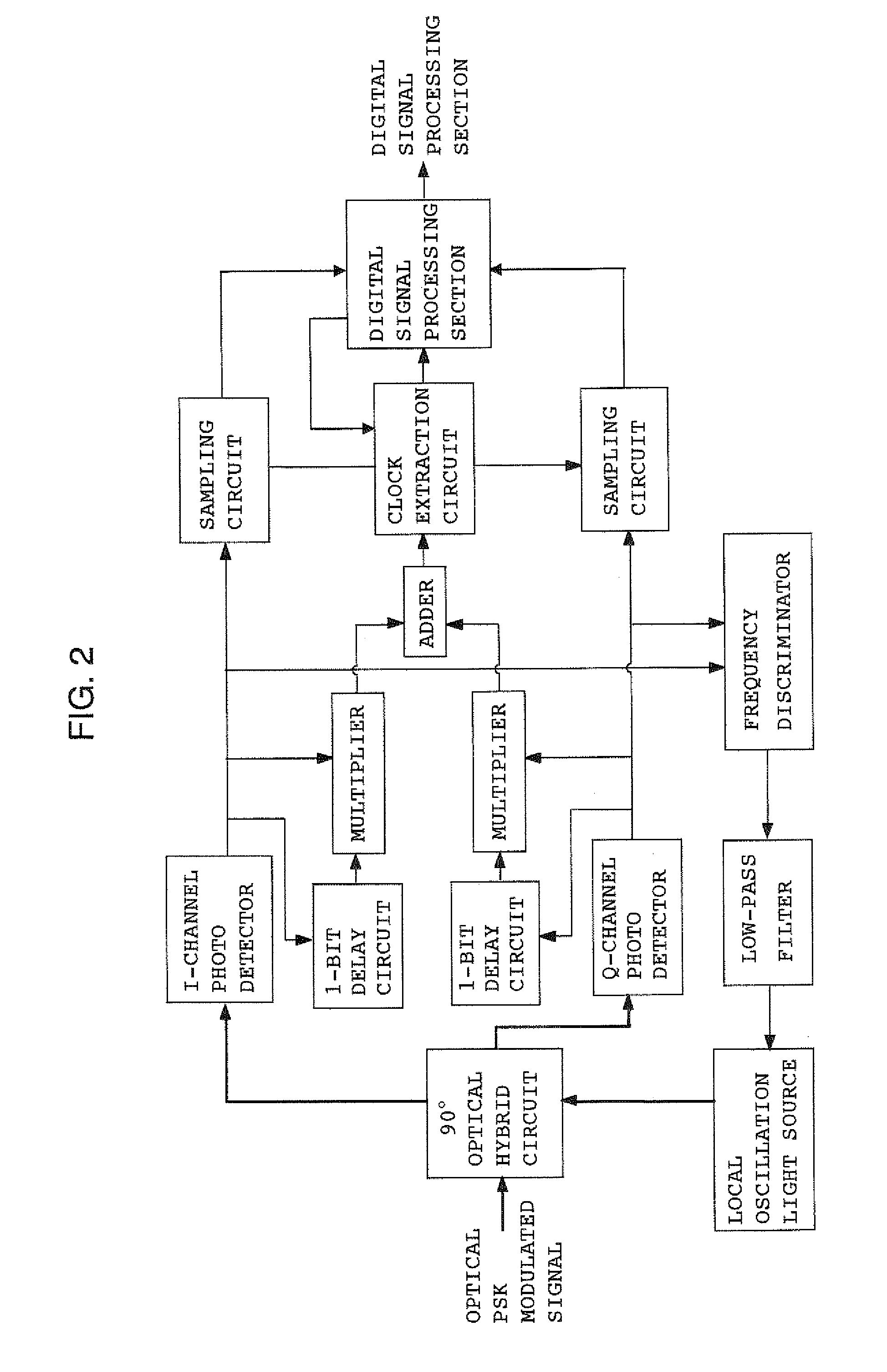
FIG. 2 is a circuit diagram of a coherent optical receiver showing the present invention. FIG. 2 shows an example in which clock signal extraction is carried out at the electrical signal level, and control of local oscillation light is performed by an analog signal. An optical PSK modulated signal and local oscillation light are mixed together by a 90-degree optical hybrid circuit, and the resultant quadrature components I and Q are led to photo detectors for I and Q channels. The electric signal output from the photo detectors and the same signals having passed through respective 1-bit-delay circuits are multiplied together by respective multipliers. Outputs from these multipliers are added together by an adder, whereby simple demodulation of the signal is carried out. From a signal (demodulated signal) produced as a result of the demodulation, a clock extraction circuit reproduces a clock whose speed is the same as that of the demodulated signal and which is synchronized therewith...


PUM


Abstract

A coherent optical receiver includes a 90-degree optical hybrid circuit to which a received signal light is input, I-channel and Q-channel photo detectors to which the outputs of the hybrid circuit are input, a clock extraction circuit which reproduces a clock whose speed is the same as a demodulated signal obtained by demodulating the received signal light and which is synchronized therewith, I-channel and Q-channel sampling circuits which sample the signal outputs from the I-channel and Q-channel photo detectors by use of the clock, and a digital signal processing section which digitally processes the sampled signals, converts them to a digital signal, and outputs the digital signal. The digital signal processing section feeds a phase offset signal detected there back to the clock extraction circuit to thereby control the phase of the clock, and compensates dispersion of light within a fiber and phase fluctuation during free-space propagation.

Description

BACKGROUND OF THE INVENTION1. Field of the InventionThe present invention relates to a coherent optical receiver which is used for terrestrial optical fiber communications, spatial optical communications between terrestrial stations, spatial optical communications between satellites, spatial optical communications between a terrestrial station and a satellite, and communications between fixed and mobile transmitters and receivers. The coherent optical receiver can be synchronized with a clock extracted from an optical phase modulated signal, and compensate propagation distortion of signals, and can receive signals modulated in two optical modulation schemes; i.e., intensity modulation and modulation for coherent communications.2. Description of the Related ArtThere has been known a coherent communication scheme which utilizes laser light's intrinsic nature as a wave, and transmits a signal by modulating the frequency or phase of the laser light, in contrast to ordinary optical commu...

Claims


Application Information

Patent Timeline
Patent Type & Authority Patents(United States)
IPC IPC(8): H04B10/06H04B10/40H04B10/07H04B10/2513H04B10/50H04B10/516H04B10/54H04B10/60H04B10/61H04B10/64
CPCH04B10/61H04B10/613H04B10/614H04B10/6165H04B10/63H04L7/033
Inventor TOYOSHIMA, MORIONISHINAGA, NOZOMUTAKAYAMA, YOSHIHISAKUNIMORI, HIROO
Owner NAT INST OF INFORMATION & COMM TECH
Why Eureka
Try Eureka