
Semiconductor device including a reduced stress configuration for metal pillars

a technology of metal pillars and semiconductors, applied in semiconductor devices, semiconductor/solid-state device details, electrical apparatus, etc., can solve the problems of affecting device reliability, reducing the density and mechanical stability or strength of low-k materials, and no longer limited signal propagation delay, so as to reduce the local stress load and reduce the probability of stress-related defects , the effect of distributing mechanical stress more efficiently

Active Publication Date: 2011-10-18
ADVANCED MICRO DEVICES INC
View PDF5 Cites 6 Cited by
  • Summary
  • Abstract
  • Description
  • Claims
  • Application Information

AI Technical Summary

Benefits of technology

This approach effectively reduces mechanical stress on the metallization system, maintaining reliability and allowing the use of sensitive dielectric materials while maintaining desired pillar height and spacing, thus enhancing the overall performance and yield of integrated circuits.

Problems solved by technology

For extremely scaled integrated circuits, the signal propagation delay is no longer limited by the circuit elements, such as field effect transistors and the like, but is limited, owing to the increased density of circuit elements requiring an even more increased number of electrical connections, by the close proximity of the metal lines, since the line-to-line capacitance is increased, in combination with a reduced conductivity of the lines due to a reduced cross-sectional area.
However, the density and mechanical stability or strength of the low-k materials may be significantly less compared to the well-approved dielectrics silicon dioxide and silicon nitride.
In addition to the problems of reduced mechanical stabilities of advanced dielectric materials having a dielectric constant of 3.0 and significantly less, device reliability may be affected by these materials during operation of sophisticated semiconductor devices due to an interaction between the chip and the package caused by a thermal mismatch of the corresponding thermal expansion of the different materials.
The thermally or mechanically induced stress may, however, also act on the lower-lying metallization layers, which may typically include low-k dielectrics or even ultra low-k (ULK) dielectric materials, thereby significantly increasing the probability of creating defects by delamination of these sensitive materials due to reduced mechanical stability and adhesion to other materials.
Moreover, during operation of the finished semiconductor device attached to a corresponding package substrate, significant mechanical stress may occur due to a significant mismatch in the thermal expansion behavior of the silicon-based semiconductor chip and the package substrate, since, in volume production of sophisticated integrated circuits, economic constraints typically require the usage of specified substrate materials for the package, such as organic materials, which typically may exhibit a different thermal conductivity and a coefficient of thermal expansion compared to the silicon chip.
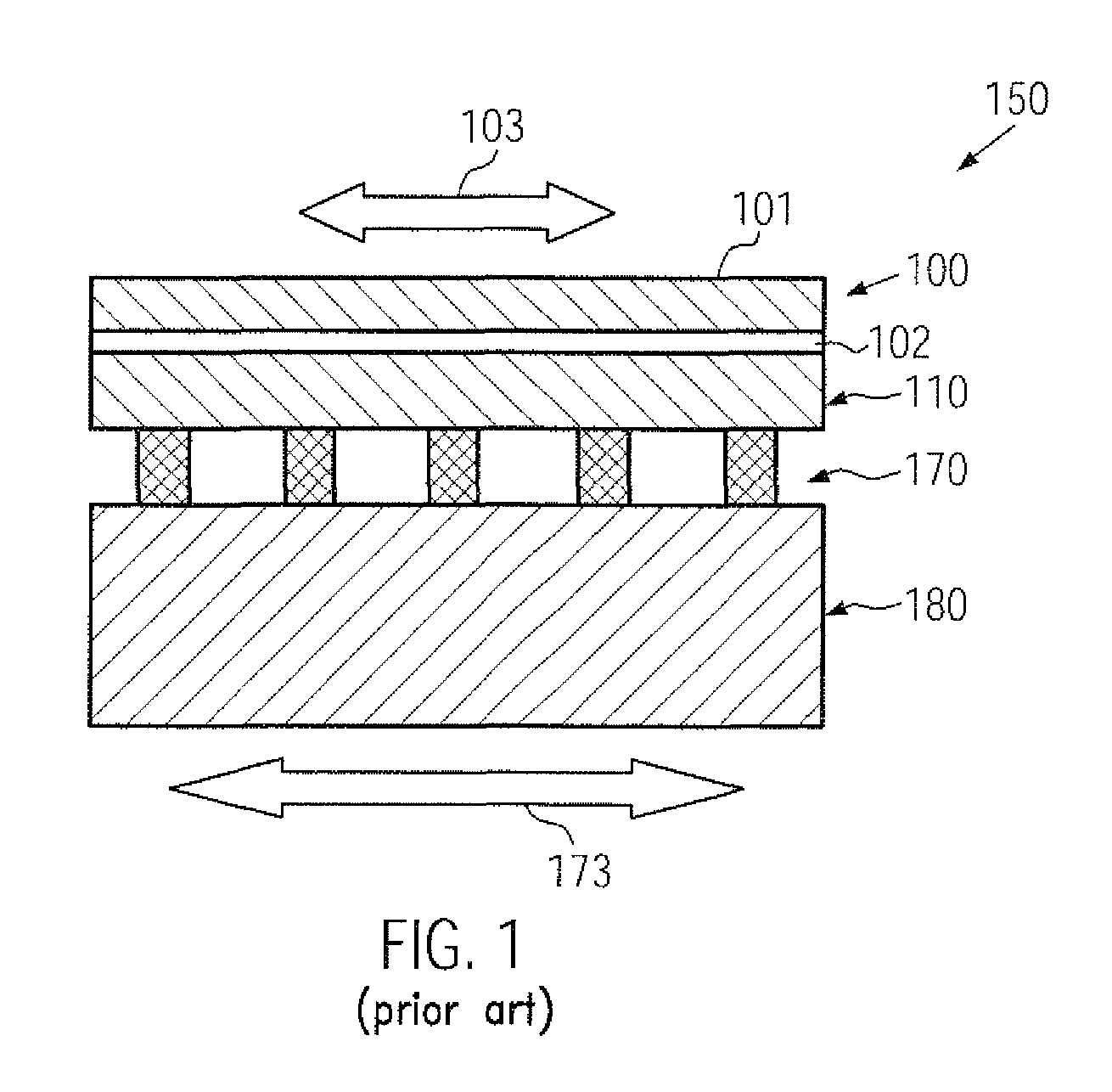
These copper pillars may, however, contribute to an even more severe interaction between the package and the metallization system of the chip, since, typically, the copper pillars are significantly less deformable compared to the bump structures, which may be advantageous in view of electrical and thermal behavior which, however, may result in even increased mechanical stress components in a locally very restricted manner, as will be described in more detail with reference to FIG. 1.
As previously discussed, the ongoing shrinkage of critical dimensions of circuit elements may result in critical dimensions of transistors on the order of magnitude of 50 nm and significantly less in presently available sophisticated semiconductor devices produced by volume production techniques.
Due to the reduced mechanical stability and the reduced adhesion of sophisticated dielectric materials, corresponding defects may occur which may affect the overall reliability of the integrated circuit 150.
In particular, the stiffness of the individual pillars of the pillar structure 170 may result in locally high sheer forces, which are transferred into the entire metallization system, thereby resulting in delamination defects and the like.
Consequently, although advanced contact regimes between a chip and a package substrate based on copper pillars may provide significant advances with respect to heat dissipation capabilities and electrical conductivity for a reduced required floor space, thereby allowing enhanced density of contact elements and / or dummy elements for heat dissipation, the increased mechanical stress induced in the metallization system may not be compatible with the reliability requirements of the semiconductor devices.
For this reason, frequently, the height of the copper pillars is reduced which, however, may be associated with a corresponding reduction of the spacing between the package substrate and the chip, which in turn may cause a non-reliable filling in of any underfill material.
Thus, corresponding voids in the underfill material may also contribute to a high degree of non-reliability, for instance caused by non-uniformities in heat conductivity and the like.
However, a corresponding manufacturing strategy is associated with increased costs due to a significantly increased manufacturing complexity in providing the solder material on top of the copper pillars.
In further conventional approaches, the metallization systems may be formed on the basis of less sensitive low-k materials or ultra low-k materials in order to enhance the mechanical stability of the metallization system, which, however, is associated with a significant reduction in electrical performance due to increased parasitic capacitances, resulting in increased signal propagation delay.

Method used


Image

  • Semiconductor device including a reduced stress configuration for metal pillars
  • Semiconductor device including a reduced stress configuration for metal pillars
  • Semiconductor device including a reduced stress configuration for metal pillars

Examples


Embodiment Construction

[0026]Various illustrative embodiments of the invention are described below. In the interest of clarity, not all features of an actual implementation are described in this specification. It will of course be appreciated that in the development of any such actual embodiment, numerous implementation-specific decisions must be made to achieve the developers' specific goals, such as compliance with system-related and business-related constraints, which will vary from one implementation to another. Moreover, it will be appreciated that such a development effort might be complex and time-consuming, but would nevertheless be a routine undertaking for those of ordinary skill in the art having the benefit of this disclosure.

[0027]The present subject matter will now be described with reference to the attached figures. Various structures, systems and devices are schematically depicted in the drawings for purposes of explanation only and so as to not obscure the present disclosure with details ...


PUM

PropertyMeasurementUnit
widthaaaaaaaaaa
widthaaaaaaaaaa
relative permittivityaaaaaaaaaa

Abstract

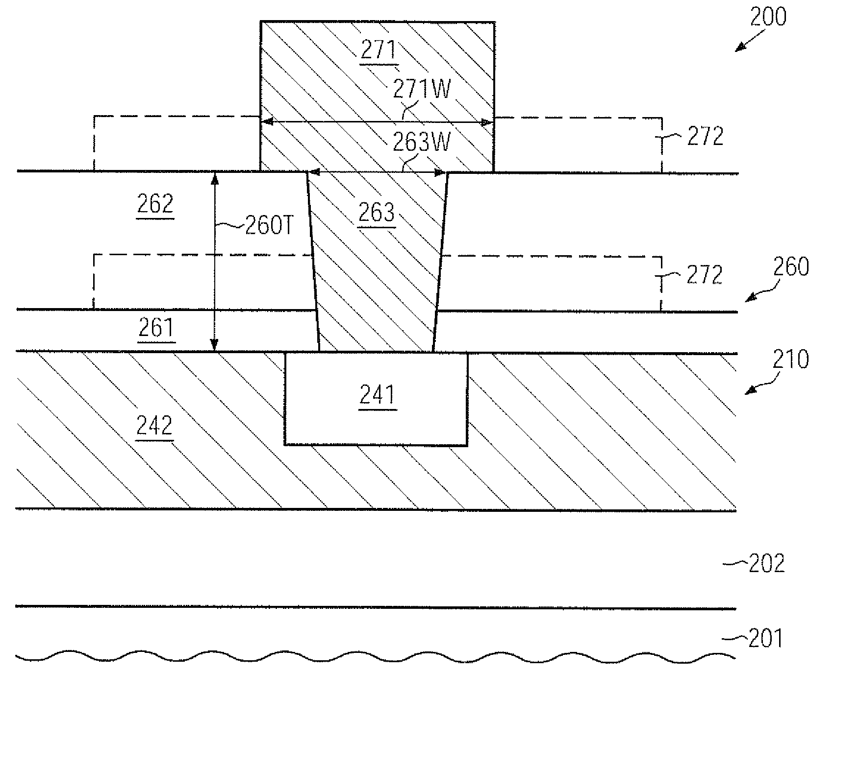
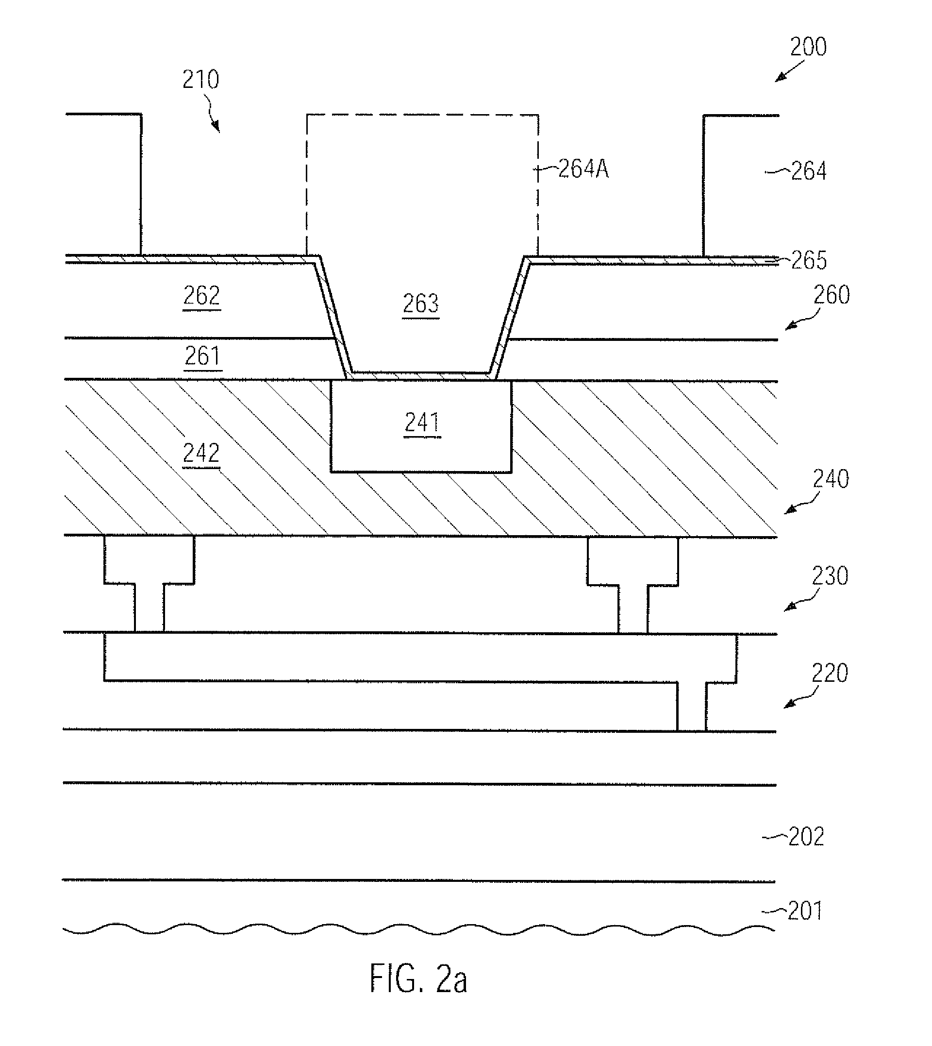
In a metallization system of a sophisticated semiconductor device, metal pillars may be provided so as to exhibit an increased efficiency in distributing any mechanical stress exerted thereon. This may be accomplished by significantly increasing the surface area of the final passivation layer that is in tight mechanical contact with the metal pillar.

Description

BACKGROUND OF THE INVENTION[0001]1. Field of the Invention[0002]Generally, the present disclosure relates to integrated circuits, and, more particularly, to the techniques for reducing chip-package interactions caused by thermal mismatch between the chip and the package.[0003]2. Description of the Related Art[0004]Semiconductor devices are typically formed on substantially disc-shaped substrates made of any appropriate material. The majority of semiconductor devices including highly complex electronic circuits are currently, and in the foreseeable future will be, manufactured on the basis of silicon, thereby rendering silicon substrates and silicon-containing substrates, such as silicon-on-insulator (SOI) substrates, viable base materials for forming semiconductor devices, such as microprocessors, SRAMs, ASICs (application specific ICs), systems on chip (SoC) and the like. The individual integrated circuits are arranged in an array on the wafer, wherein most of the manufacturing ste...

Claims


Application Information

Patent Timeline
Patent Type & Authority Patents(United States)
IPC IPC(8): H01L29/40
CPCH01L23/3171H01L23/522H01L23/562H01L24/03H01L24/05H01L2924/0002H01L2924/00014H01L2924/1306H01L2924/351H01L2224/0401H01L2224/02166H01L2924/10253H01L2924/0105H01L2924/01024H01L2924/01019H01L2924/01006H01L2924/30105H01L2924/19043H01L2924/19041H01L2924/1433H01L24/11H01L24/13H01L2224/05093H01L2224/05096H01L2224/05556H01L2224/05567H01L2224/05624H01L2224/05647H01L2224/1147H01L2224/1191H01L2224/13007H01L2224/13022H01L2924/01004H01L2924/01013H01L2924/01014H01L2924/01029H01L2924/01032H01L2924/01033H01L2924/01047H01L2924/01073H01L2924/01074H01L2924/01078H01L2924/01082H01L2924/014H01L2924/04953H01L2924/05042H01L2924/14H01L2924/00H01L2224/05552H01L2224/13023H01L23/31H01L23/485
Inventor PLATZ, ALEXANDERLEHR, MATTHIASKUECHENMEISTER, FRANK
Owner ADVANCED MICRO DEVICES INC
Learn More