
Conductive member, process cartridge using the conductive member, and image forming device using the process cartridge

a technology of conductive parts and process cartridges, which is applied in the direction of electrographic process apparatus, instruments, and discharges, etc., can solve the problems of reducing the charging performance of toners, difficult to uniformly maintain space, and water absorption properties that cannot be easily absorbed, so as to increase the blending ratio of thermoplastic resins, reduce water absorption properties, and increase resistance

Inactive Publication Date: 2011-11-22
RICOH KK
View PDF20 Cites 1 Cited by
  • Summary
  • Abstract
  • Description
  • Claims
  • Application Information

AI Technical Summary

Benefits of technology

The present invention relates to a conductive member that reduces water absorption and has a small environmental variation of a space between an image carrier and the conductive member, while maintaining its conductive property. The invention also provides a process cartridge and an image forming device that use the conductive member. The invention solves the problem of increased resistance and image error caused by environmental variations of the space between the charging roller and the photoconductor. The invention achieves this by blending a fibrous polymer with an insulating property and an affinity for the thermoplastic resin, without increasing the blending ratio of the thermoplastic resin. The invention also includes a space holding member that constantly maintains a space between the image carrier and the electric resistance-adjusting layer, and a graft copolymer with an affinity for both the fibrous polymer and the thermoplastic resin. The fibrous polymer used in the invention includes wholly aromatic polyamide fiber, wholly aromatic polyester fiber, and PBO. The electrolyte salt used in the invention includes perchlorate, fluorine-containing organic anion salt, and organic phosphonium salt. The conductive member charges the image carrier and the process cartridge and image forming device using the conductive member have improved performance and stability.

Problems solved by technology

1. Charging roller track: The component of the charging roller exudes from the charging roller, and then adheres onto the surface of the photoconductor. If this adhesion is developed, the track of the charging roller remains on the surface of the photoconductor.
2. Charging noise: When applying an alternating voltage to the charging roller, the charging roller which has contact with the photoconductor vibrates, causing charging noise.
3. The decrease in the charging performance by the adherence of toners on the photoconductor to the charging roller: Especially, by the above-described exuding, the toners easily adhere onto the charging roller.
4. The component of the charging roller easily adheres onto the photo conductor.
5. The permanent deformation of the charging roller which is caused when stopping the photoconductor for a long period of time.
In the close charging method, when the charging roller formed by such an elastic body is used, the following problems are caused.
However, since the charging roller is made of the elastic body, it is difficult to uniformly maintain the space because of the deformation of the elastic body.
As a result, displacement in the charged potential and an uneven image resulting from the displacement are caused.
2. The vulcanized rubber material which forms the elastic body deteriorates with age and easily deforms.
As a result, a charging error is partially caused, which causes an image error.
However, a low-molecular-weight ion-conductive material such as an electrolyte salt has a property which easily bleeds out on the surface of the matrix resin.
For this reason, the toners are firmly fixed onto the surface of the charging roller when bleeding out, resulting in an image error.
By only using the high-molecular form ion conductive material, the resistance-adjusting layer can not be controlled in the semi-conductive property range because the resistance value of the resistance-adjusting layer is high.
Accordingly, when the high-monocular form ion conductive material is used as the resistance-adjusting layer of the charging roller in the close charging method, the environmental variations of the space between the charging roller and the photoconductor are increased, and the charging performance is decreased, resulting in an image error.
In this case, since the discharge product on the photoconductor adheres onto the charging roller, the conductive property of that portion is lowered, resulting in an image error.
On the other hand, since the size of the space is increased in low-temperature and low-humidity environment, the discharge from the charging roller to the photoconductor becomes uneven, resulting in an image error.
In this case, the resistance is also increased, so that the conductive property required for the charging roller can not be obtained.

Method used


Image

  • Conductive member, process cartridge using the conductive member, and image forming device using the process cartridge
  • Conductive member, process cartridge using the conductive member, and image forming device using the process cartridge
  • Conductive member, process cartridge using the conductive member, and image forming device using the process cartridge

Examples


embodiment 1

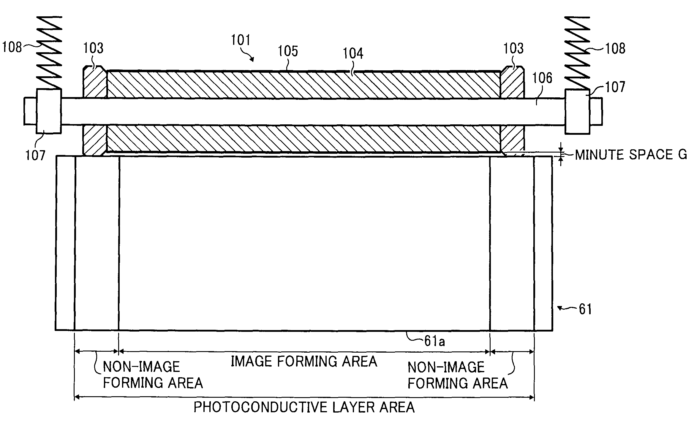
[0128]A resin composition (volume resistivity value: 2×10⁸ Ωcm) in which the following prescription 1 was melted and kneaded at 220° C. was coated on a core shaft 106 (8 mm in outer diameter) which is a conductive supporting body made of a stainless-steel by means of injection molding, and an electric resistance-adjusting layer 104 was formed. The typical structure of the blended fibrous polymer is as illustrated in FIG. 6.

[0129]Prescription 1

[0130]A: IRGASTAT P18 (made by Chiba Specialty Chemicals, Inc.) 55 pts.wt.

[0131](polyether ester amide, A contains sodium perchlorate)

[0132]B: Meta from aramid fiber (Conex 2.2 dtex, 1 mm made by Teijin Techno Products Limited) 5 pts.wt.

[0133](Fibrous Polymer)

[0134]D: ABS resin (DENKA ABS, GR-3000 made by DENKI KAGAKU KOGYO KABUSHIKI KAISHA) 40 pts.wt.

[0135](Thermoplastic Resin of High Hardness)

[0136]With respect to 100 pts.wt. of the mixture of A, B and D,

[0137]E: polycarbonate-glycidylmethacrylate-styrene-acrylonitrile copolymer (MODIPER C L4...

embodiment 2

[0143]A resin composition (volume resistivity value: 2×10⁹ Ωcm) in which the following prescription 2 was melted and kneaded at 220° C. was coated on a core shaft 106 (8 mm in outer diameter) made of a stainless-steel by means of injection molding, and an electric resistance layer 104 was formed. The typical structure of the blended fibrous polymer is as illustrated in FIG. 7.

[0144]Prescription 2

[0145]A: TPAE-10HP (made by FUJI KASEI KOGYO CO., LTD.) 50 pts.wt.

[0146](Polyether Ester Amide)

[0147]B: Para form aramid fiber (Technora 1.7 dtexd, 1 mm made by Teijin Techno Products Limited) 10 pts.wt.

[0148](Fibrous Polymer)

[0149]D: ABS resin (DENKA ABS GR-0500 made by DENKI KAGAKU KOGYO KABUSHIKI KAISHA) 40 pts.wt.

[0150](Thermoplastic Resin of High Hardness)

[0151]With respect to 100 pts.wt. of the mixture of A, B, and D,

[0152]E: polycarbonate-glycidylmethacrylate-styrene-acrylonitrile copolymer (MODIPER C L440-G made by NOF CORPORATION) 4.5 pts.wt. (graft copolymer)

[0153]C: trifluorometha...

embodiment 3

[0155]A resin composition (volume resistivity value: 3×10⁸ Ωcm) in which the following prescription 3 was melted and kneaded at 230° C. was coated on a core shaft 106 (8 mm in outer diameter) made of a stainless-steel by means of injection molding, and an electric resistance-adjusting layer 104 was formed. The typical structure of the blended fibrous polymer is as illustrated in FIG. 8.

[0156]Prescription 3

[0157]A: Sankonol TBX-65 (made by Sanko Chemical Ind, Co., Ltd.) 60 pts.wt.

[0158](Polyether Ester Amide, a Contains Trifluoromethanesulfonate Lithium).

[0159]B: Para form aramid fiber (Twaron 1.7 dtex, 0.25 mm made by Teijin Techno Products) 10 pts.wt. (fibrous polymer)

[0160]D: Polycarbonate resin (Iupilon H-4000 made by Mitsubishi Engineering-Plastics Corporation) 30 pts.wt. (thermoplastic resin of high hardness)

[0161]With respect to 100 pts.wt. of the mixture of A, B, and D,

[0162]E: Polycarbonate-glycidylmethacrylate-styrene-acrylonitrile copolymer (MODIPER C L440-G made by NOF CO...


PUM


Abstract

A conductive member includes, a conductive supporting body, an electric resistance-adjusting layer formed in the conductive supporting body, and a space holding member which is formed on each end of the electric resistance-adjusting layer and has a material different from a material of the electric resistance-adjusting layer, the space holding member constantly maintaining a space between an image carrier and the electric resistance-adjusting layer, and the electric resistance-adjusting layer including a resin composition having a thermoplastic resin (A) containing at least an ether group, a fibrous polymer (B), which do not melt in (A) and has an aromatic skeleton in a molecule, and an electrolyte salt (C).

Description

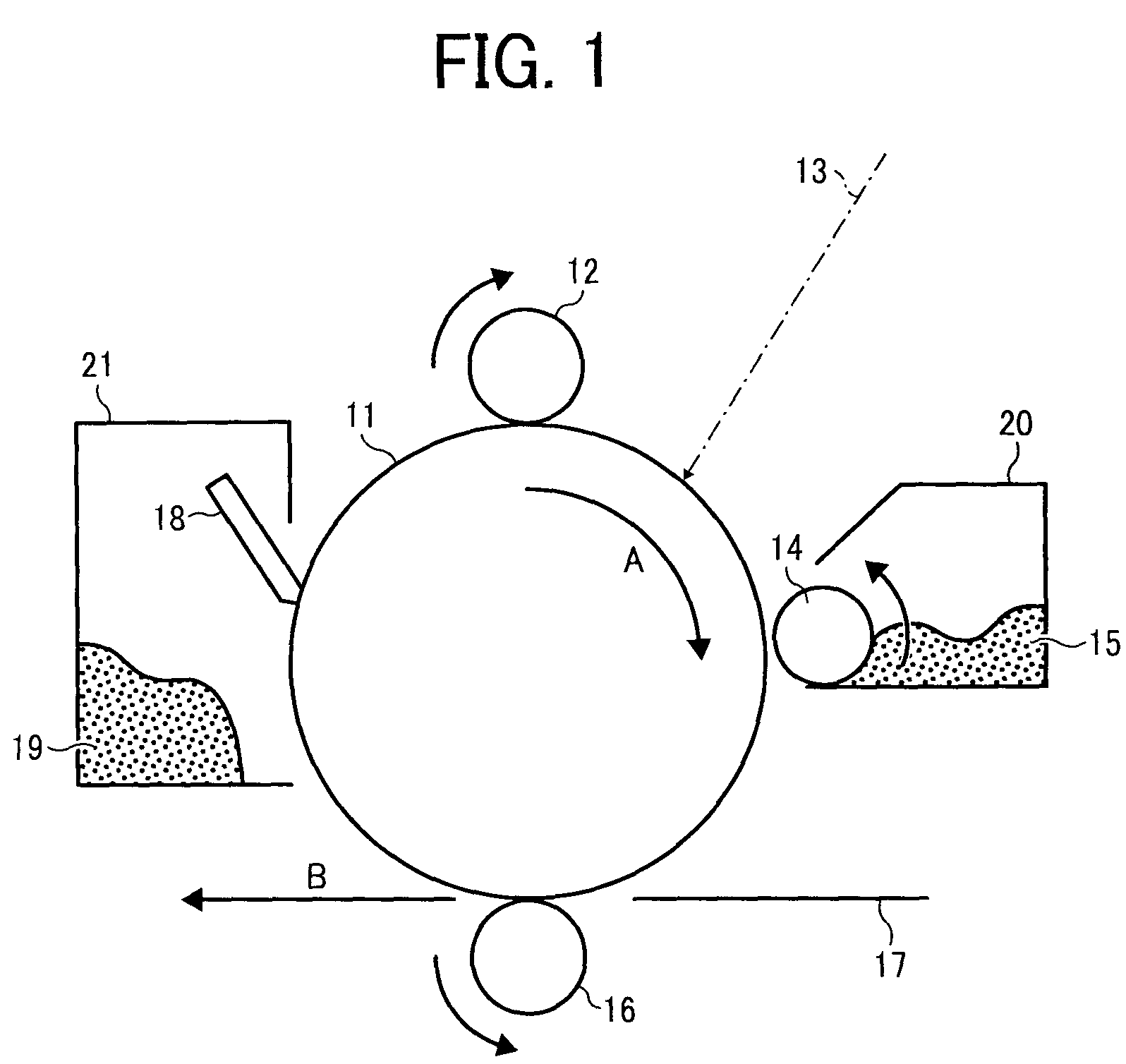
PRIORITY CLAIM[0001]The present application is based on and claims priority from Japanese Patent Application No. 2007-309813, filed on Nov. 30, 2007, the disclosure of which is hereby incorporated by reference in its entirety.BACKGROUND OF THE INVENTION[0002]1. Technical Field[0003]This disclosure relates to a conductive member, a process cartridge using the conductive member, and an image forming device using the process cartridge.[0004]2. Description of the Related Art[0005]In an electrophotographic process such as that carried out in a copier, a laser printer, or a facsimile, a conductive member is conventionally used as a charging member, which performs a charging process on an image carrier (photoconductor), and a transfer member, which conducts a transfer process on toners on the photoconductor.[0006]FIG. 1 is a schematic view illustrating an image forming device.[0007]Referring to FIG. 1, the image forming device includes an image carrier 11 (photoconductor) onto which an ele...

Claims


Application Information

Patent Timeline
Patent Type & Authority Patents(United States)
IPC IPC(8): G03G15/02
CPCG03G15/02
Inventor OSHIMA, TADAYUKI
Owner RICOH KK
Learn More