
System, method and device for positioning a target located within soft tissue in a path of an instrument

a target and soft tissue technology, applied in the field of systems, methods and devices for positioning a target located within soft tissue in the path of an instrument, can solve the problems of poor maneuverability of the biopsy needle, architectural distortion and target deflection, and significant technical challenges, and achieve the effect of minimizing the tracking error in the position of the targ

Inactive Publication Date: 2011-11-29
VANDERBILT UNIV
View PDF5 Cites 59 Cited by
  • Summary
  • Abstract
  • Description
  • Claims
  • Application Information

AI Technical Summary

Benefits of technology

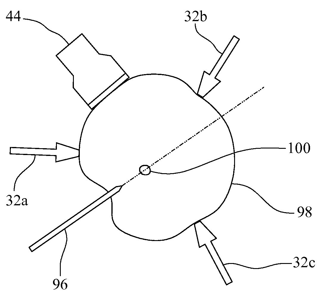
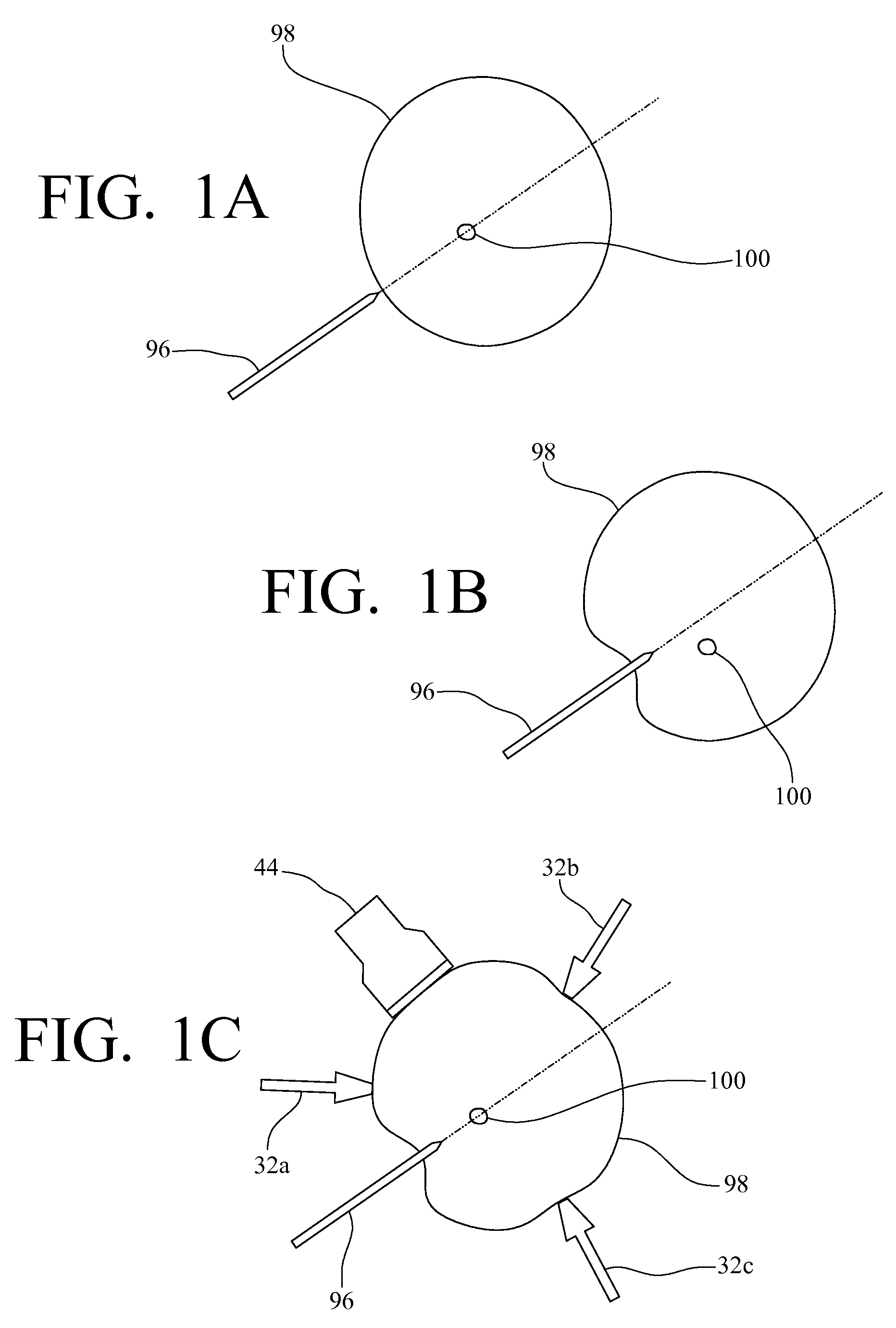
[0016]The system, method and device described herein guide a target towards a line of insertion of an instrument, such as a needle, instead of steering the instrument towards the target during insertion. The system, method and device use a target manipulation system that positions the target inline with the instrument during insertion. The real-time target manipulation system presented is a set of position controlled force applicators. These applicators are placed around the soft tissue, such as a breast, during the instrument insertion procedure. They control the position of the target, by applying forces on the surface of the soft tissue, such that the target is always placed inline with the instrument. A PI or PID controller minimizes the tracking error in the position of the target. In this approach, instrument insertion force is treated as a disturbance to the system.
[0019]The robotic device has the following advantages: (a) success rate of the procedure (as defined by the number of insertions required at a particular site to successfully sample the target) will be increased since the target is accurately positioned inline with the instrument; (b) since instrument alignment, imaging probe positioning, target localization and soft tissue stabilization are automated, it will likely minimize fatigue of the surgeon; (c) since the instrument is not steered inside the soft tissue, and number of insertions reduced, tissue damage is also minimized (patient discomfort is reduced) and the structural integrity of the tissue specimen is preserved; and (d) by improving accuracy of the procedure, it will potentially enhance the diagnostic outcome by reducing false negatives.

Problems solved by technology

Despite many benefits of needle biopsy, there are significant technical challenges concerning accurate steering and precise placement of a biopsy needle at the target in breast tissue.
To successfully remove a suspicious small targeted lump (e.g., less than 5 mm in diameter) various issues must be addressed, such as architectural distortion and target deflection during needle insertion and poor maneuverability of the biopsy needle.
Although mammography, sonography, and magnetic resonance imaging (MRI) techniques have significantly improved early detection of breast cancer, accurate placement of a biopsy needle at the target location and reliable collection of target tissue remain challenging tasks.
For a few years three dimensional (3D) US systems have been available, but they are not as widely used as two dimensional (2D) US systems because of their high cost.
Hence the entire 3D volume cannot be reconstructed in real-time.
This technique is not applicable to breast biopsies due to the deformation of the breast during needle insertion.
Despite numerous benefits of needle biopsy, however, there are significant challenges concerning accurate steering and precise placement of a biopsy needle at the target (the word target as used herein refers to a tumor, a lesion or just a suspected region of tissue) in breast tissue.
First, as the needle is inserted, large tissue deformation causes the target to move away from the line of insertion of the needle.
It is critical to orient the imaging plane parallel to the needle, otherwise a false impression of the needle tip causes sampling errors.
Since stabilization of the breast is problematic and steering of the needle inside the breast is extremely difficult, many insertion attempts may be required to successfully sample the target.
This may cause architectural damage to the tissue, excessive bleeding obscuring the guiding images, surgeons' fatigue and patient discomfort.
Currently available commercial biopsy instruments (Mammotome®, Vacora® etc.) do not compensate for target movement during needle insertion.
1998 [5] and Cleary et al., 2001 [6]) do not provide real-time trajectory correction to overcome error due to target movement.
Steerable devices can only be used with small caliber needles and hence are unsuitable for core needle biopsies.
Though this system potentially reduces the number of insertions required to sample the target, maneuvering a needle inside the breast causes tissue damage.
Even though these systems greatly reduce the difficulty of acquiring US images, the target cannot be tracked in real-time if it moves out of the imaging plane of the probe.
Due to needle insertion and target manipulation, large tissue deformation occurs inside the breast which prohibits application of this technique.
There has been some work on developing such hybrid controllers in other non-analogous fields, such as industrial robotics, medicine and manufacturing (see: Antsaklis, 2000 [23]), however no work has been done with respect to such a system for biopsy purposes.

Method used


Image

  • System, method and device for positioning a target located within soft tissue in a path of an instrument
  • System, method and device for positioning a target located within soft tissue in a path of an instrument
  • System, method and device for positioning a target located within soft tissue in a path of an instrument

Examples


experiment 1

To Demonstrate Accuracy of Target Positioning Using External Force on the Surface of the Phantom During Needle Insertion

[0112]For the first experiment, the target is initially located at the origin and the needle is inserted along the Y axis. Due to inhomogeneity in the phantom the target moves away from the needle path during insertion. Linear actuators are positioned along the X axis to steer the target towards the needle path (Y axis). During this experiment the force applied by the needle on the phantom is treated as a disturbance to the system. The task of the controller is to position the target on the Y axis. The position of the target along the Y axis is not controlled since the needle will intersect with the target no matter where it is located on the Y axis. In this experiment a PI controller is used for controlling the position of the target.

[0113]FIG. 11 shows a plot of the position response of the target (along the X axis) in an inhomogeneous phantoms. This phantom has ...

experiment 2

To Demonstrate Coordination of Target Positioning and Dynamic Target Tracking During Needle Insertion

[0116]For the second experiment, linear actuators are used to position the target during a needle insertion task. The target is initially located at the origin and the needle is inserted along the Y axis. The US probe is placed over the phantom such that the imaging plane (XZ plane) is orthogonal to the needle insertion direction. During a biopsy procedure, the imaging plane has to be oriented along the needle insertion direction. In this experiment the US probe is placed orthogonally to demonstrate the ability of the system to track the target when it moves out of the imaging plane during a real-time needle insertion procedure.

[0117]In this experiment, during needle insertion, the target moves away from the needle path and out of the imaging plane of the US probe. Two linear actuators positioned along the X axis are used to steer the target towards the needle path (Y axis), similar ...

experiment 3

To Demonstrate Reliability of the Contact Detection Algorithm

[0121]In this experiment target manipulation and tracking are disabled. Position of the phantom is fixed and the US probe is moved normal to the surface of the phantom. FIG. 15A shows the movement of the probe. The X axis represents the surface of the phantom. The US probe is in contact with the phantom if the probe position is nonnegative and the probe breaks contact with the phantom if its position is negative. FIG. 15B shows the contact state of the probe. If the US probe is in contact, it is represented by 1 (True). If the US probe is not in contact, it is represented by 0 (False). The contact state is determined using the algorithm presented above. Comparing FIG. 15A and FIG. 15B, it is observed that the algorithm reliably predicts contact state transitions of the probe. During a biopsy procedure, position data cannot be used to detect contact state transitions due to deformation of the breast. Hence, contact state de...


PUM


Abstract

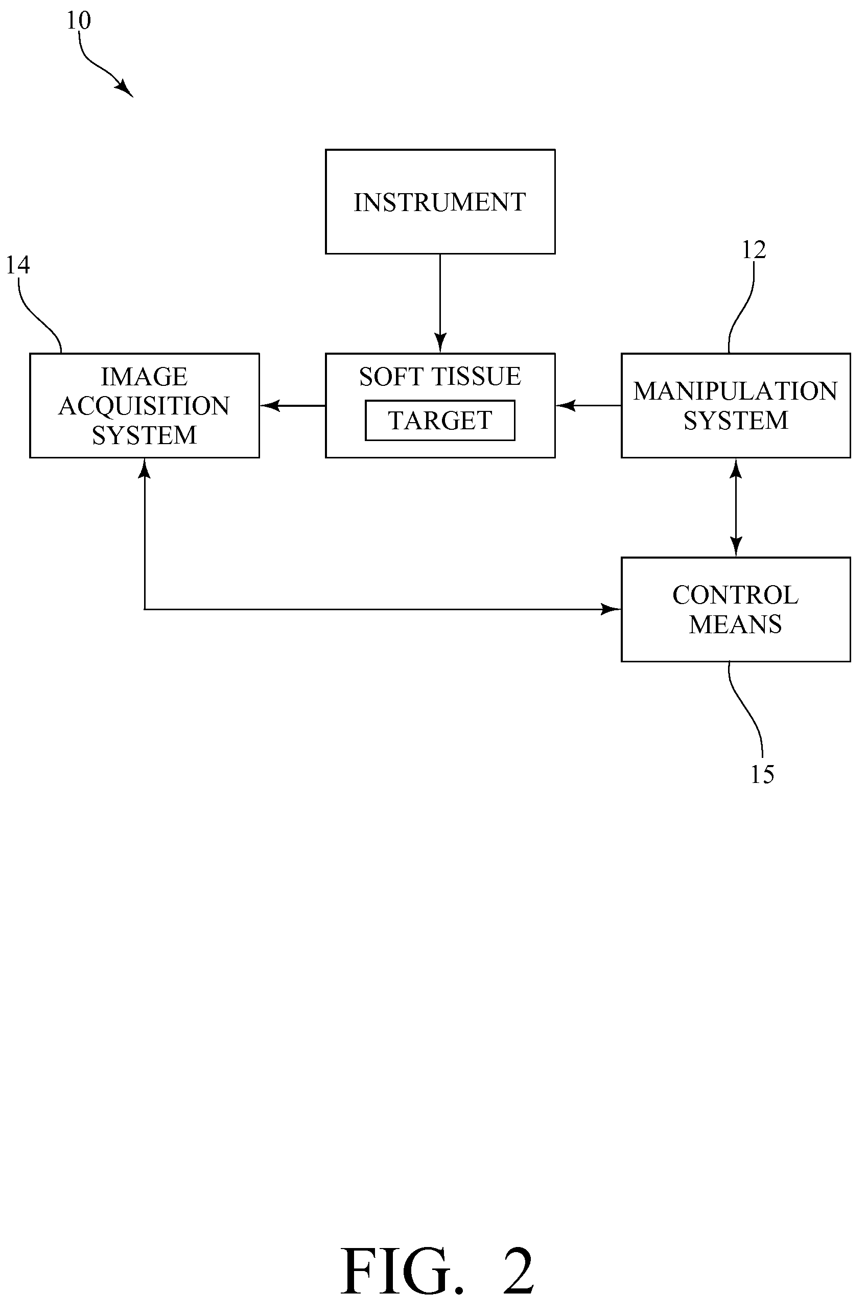
A system, method and device for positioning a target located within soft tissue in a path of an instrument inserted into the soft tissue includes: a manipulation system including a plurality of force applicators positioned around the soft tissue containing the target; an image acquisition system including an imaging probe for obtaining data for generating an image of the soft tissue containing the target; a detection means for detecting deflection of the target using the data from the imaging probe; and a control means for actuating the plurality of force applicators to apply forces on the soft tissue in response to a detected deflection of the target to move the target back in line with the path of the instrument. In an exemplary embodiment, the soft tissue is a breast, the imaging probe is an ultrasound imaging probe, and the instrument is a biopsy needle.

Description

CROSS-REFERENCE TO RELATED APPLICATIONS[0001]This application claims the benefit of U.S. Provisional Patent Application No. 60 / 938,605, filed May 17, 2007, and U.S. Provisional Patent Application No. 60 / 971,745, filed Sep. 12, 2007, the entire disclosures of which are hereby incorporated by reference.STATEMENT REGARDING FEDERALLY SPONSORED RESEARCH OR DEVELOPMENT[0002]Not applicable.THE NAMES OF THE PARTIES TO A JOINT RESEARCH AGREEMENT[0003]Not applicable.INCORPORATION-BY-REFERENCE OF MATERIAL SUBMITTED ON A COMPACT DISC[0004]Not applicable.TECHNICAL FIELD[0005]The presently-disclosed subject matter relates to systems, methods, and devices for positioning a target located within soft tissue in a path of an instrument, including systems, methods, and devices for performing breast tissue biopsies.BACKGROUND[0006]Breast cancer is the most common cancer among American women and the second leading cause of cancer death in women. American Cancer Society, 2007 [1]. However, early detectio...

Claims


Application Information

Patent Timeline
Patent Type & Authority Patents(United States)
IPC IPC(8): A61B8/00
CPCA61B19/201A61B8/4245A61B8/587A61B19/22A61B19/5244A61B2017/3409A61B2017/3413A61B2019/5259A61B2019/5276A61B2019/5295A61B2019/205A61B34/20A61B34/70A61B90/11A61B90/17A61B2034/2059A61B2090/367A61B2090/378
Inventor SARKAR, NILANJANPODDER, TARUN KANTIMALLAPRAGADA, VISHNU
Owner VANDERBILT UNIV
Learn More