Pedicle dart system

a technology of pedicle and screw, applied in the field of spine, can solve the problems of inaccurate placement of screw, inability to properly place screw, and inability to properly place screw, and achieve the effect of superior surgical control a distance from the spine and large threaded fixation

Active Publication Date: 2011-12-13
LIFE SPINE INC
View PDF10 Cites 10 Cited by
  • Summary
  • Abstract
  • Description
  • Claims
  • Application Information

AI Technical Summary

Benefits of technology

[0009]The system and method of the invention, enables a staged location and entry into the pedicle for providing insertive, progressively larger threaded fixation and superior surgical control a distance from the spine. The pedicle dart system can be used in conjunction with or without a Jamshedi trocar and sleeve, in order to give additional advantage for early focussing of the early guided location and initial placement of the pedicle dart system.
[0010]The pedicle dart system is simple and has a small number of components. These components include a guide pin, a pedicle dart fastener (preferably having some control structure for easy manual rotation) having a central opening to accommodate the guide pin, an indexed sleeve (preferably with handle) having a central opening to accommodate the threaded pedicle dart fastener to hold the dart to the sleeve. The threaded pedicle dart fastener should have a manual control surface which facilitates it axial rotation with respect to the indexed sleeve. The indexed sleeve preferably has a handle to enable rotational turning of the pedicle dart into the pedicle for ease and control.

Problems solved by technology

This process is difficult, even where there is direction visualization of the area of the pedicle where insertion will occur.
Because placement, angularity, and turning insertion is a complex process, the insertion process often leads to inaccurate placement of the screw.
Such inaccurate placement can have serious neurological, vascular, and dural leak complications.
Further, inaccurate placement of the pedicle screw may result in damage such that screw insertion either cannot be achieved, or if it can be achieved it may require additional surgical procedures for correction and may not enable the holding strength necessary.
This most often results in significant blood loss during this exposure phase of the operation, which is only one part of a multiple step operative procedure.
Any problems at any stage of an operation can risk the patient's health and compound any unexpected routine problems which occur.
The surgical practitioner is faced with the choice between high exposure and a good view, versus a more limited exposure with a much poorer view and a heightened risk of a wrong insertion of the pedicle screw.
Further, when a high exposure is attempted, excess bleeding is often encountered directly due to the higher exposure which can even further obscure visualization and may require blood transfusion with its associated complications.
Any extra time on the operating table, whether caused by excess bleeding or not places the patient in greater danger.
But excess bleeding combined with longer operating time due to poor visibility, and corrective measures required to find the appropriate placement of the pedicle screw can be disastrous.
All of the above effects contribute to surgeon fatigue, which can result in increased operative complications.
Currently available surgical retractor systems fail to fulfill all of the above requirements.
Consequently there is a severe need for structures and procedures to meet such requirement.

Method used


Image

  • Pedicle dart system
  • Pedicle dart system
  • Pedicle dart system

Examples


Embodiment Construction

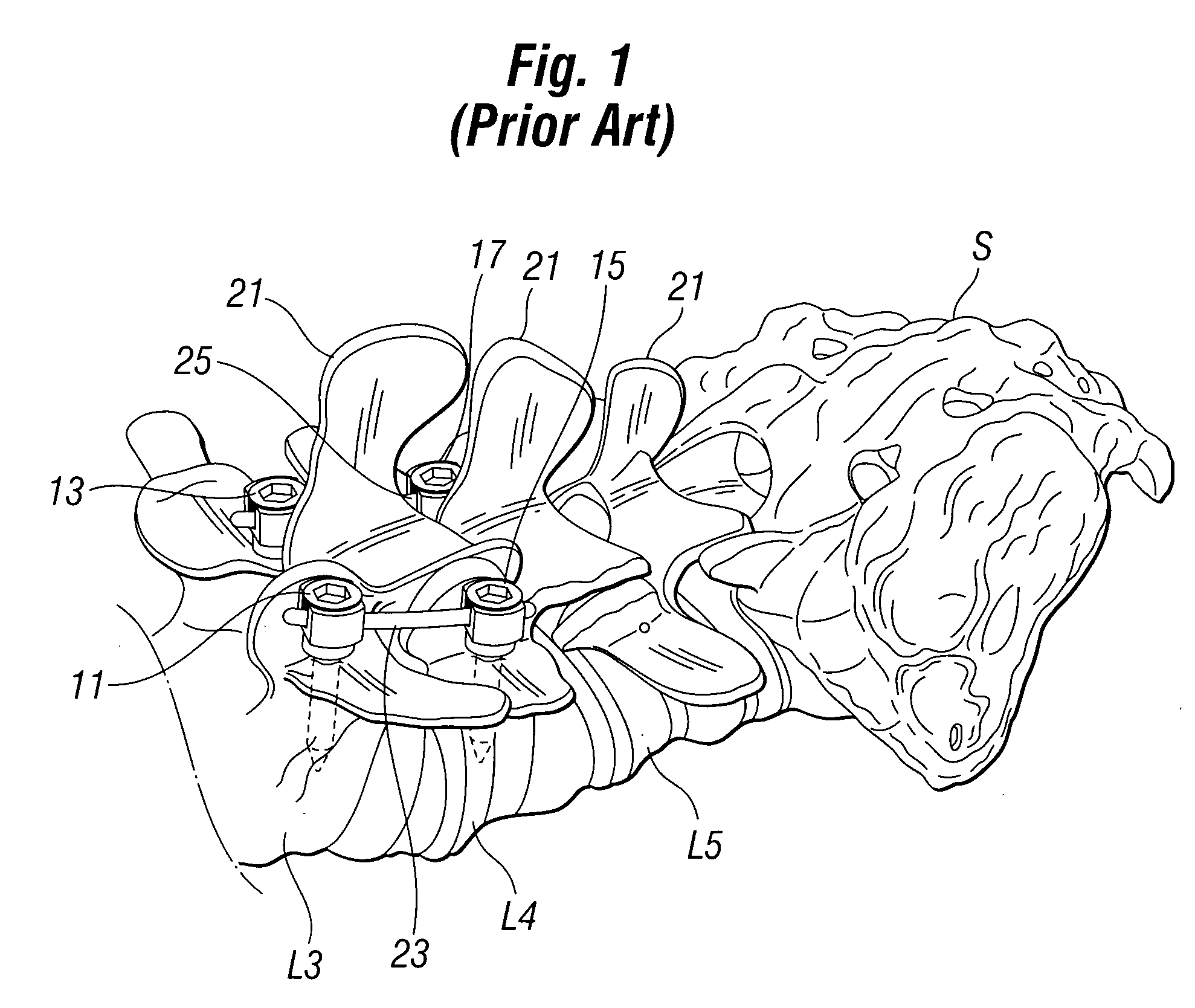
[0049]A detailed description of the preferred embodiment will be best begun by examining a perspective view of the lower lumbar vertebrae L3, L4, L5 and sacrum S shown in perspective in FIG. 1. In operative procedures in which work is to be done between two adjacent vertebrae, those two vertebrae must be fixed and held apart so that the space between those vertebrae is maintained. Traditionally this has been done by using conventional pedicle screws 11, 13, 15 and 17 seen in FIG. 1. The conventional pedicle screws 11, 13, 15 and 17 engage significant bone mass by placement through the pedicle structure of each vertebra into which they are placed. In the three dimensional view of FIG. 1, the conventional pedicle screws 11, 13, 15 and 17 seem to have an open placement, during an actual surgical procedure on a patient, the pedicle screws 11, 13, 15 and 17 must be located through and despite significant layers of muscular tissue.

[0050]As previously discussed, dissection of the muscles s...


PUM


Abstract

Minimal Invasive Spine Surgery (MISS) as a surgical approach is increasingly utilized because of the advantages it offers over conventional spine surgery. The smaller incision results in decreased tissue damage, less blood loss, decreased hospital stay & faster postoperative recovery. The drawbacks of MISS are the long learning curve of working through a smaller incision, longer length of surgery, & potential higher complication rate due to compromised visual field. These limitations can be overcome by more effectively using imaging and navigational devices. The pedicle device simplifies the hardest part of MISS instrumented fusion of conventional pedicle screw insertion by introducing a percutaneous temporary device to locate and create the channel for later conventional pedicle screw implantation using available imaging techniques. This results in faster conventional pedicle screw insertion with precision, thereby decreasing implantation error and minimizing soft tissue injury and blood loss, as well as neurological, vascular, and dural injuries and complications.

Description

FIELD OF THE INVENTION[0001]The present invention relates to improvements in the field of spine and more particularly to a system for location, placement, and insertion of pedicle darts which is applicable to both MIS and open surgical technique which allows for more exacting and rapid placement and angular insertion of fixation members into the spinal pedicle, to facilitate one of the most difficult phases of spine surgery. Greater access, angularity and location is allowed independent of manipulation of the pedicle darts into bony tissue, resulting in a reduced time necessary to complete one of the more difficult phases of the operative procedure. The result is increased safety of placement and insertion, as well as less time spent on the operating table.BACKGROUND OF THE INVENTION[0002]Lumbar Diskectomy and other spinal techniques require external stabilization of lumbar vertebrae to either side of the vertebra being treated. Traditional pedicle screw insertion has required the i...

Claims


Application Information

Patent Timeline
Patent Type & Authority Patents(United States)
IPC IPC(8): A61B17/32
CPCA61B17/1671A61B17/7001A61B17/7082A61B17/861A61B17/863A61B17/8635A61B17/864
Inventor HAMADA, JAMES S.
Owner LIFE SPINE INC
Why Eureka
Try Eureka