Method of fabricating group-III nitride semiconductor laser device

a technology of semiconductor lasers and semiconductors, applied in the direction of semiconductor lasers, wave amplification devices, electrical equipment, etc., can solve the problems of heavy process conditions, unable to use conventional cleaved facets in the orientation of laser waveguides, etc., and achieve the effect of reducing the threshold current and lowering the threshold curren

Inactive Publication Date: 2012-01-31
SUMITOMO ELECTRIC IND LTD
View PDF3 Cites 26 Cited by
  • Summary
  • Abstract
  • Description
  • Claims
  • Application Information

AI Technical Summary

Benefits of technology

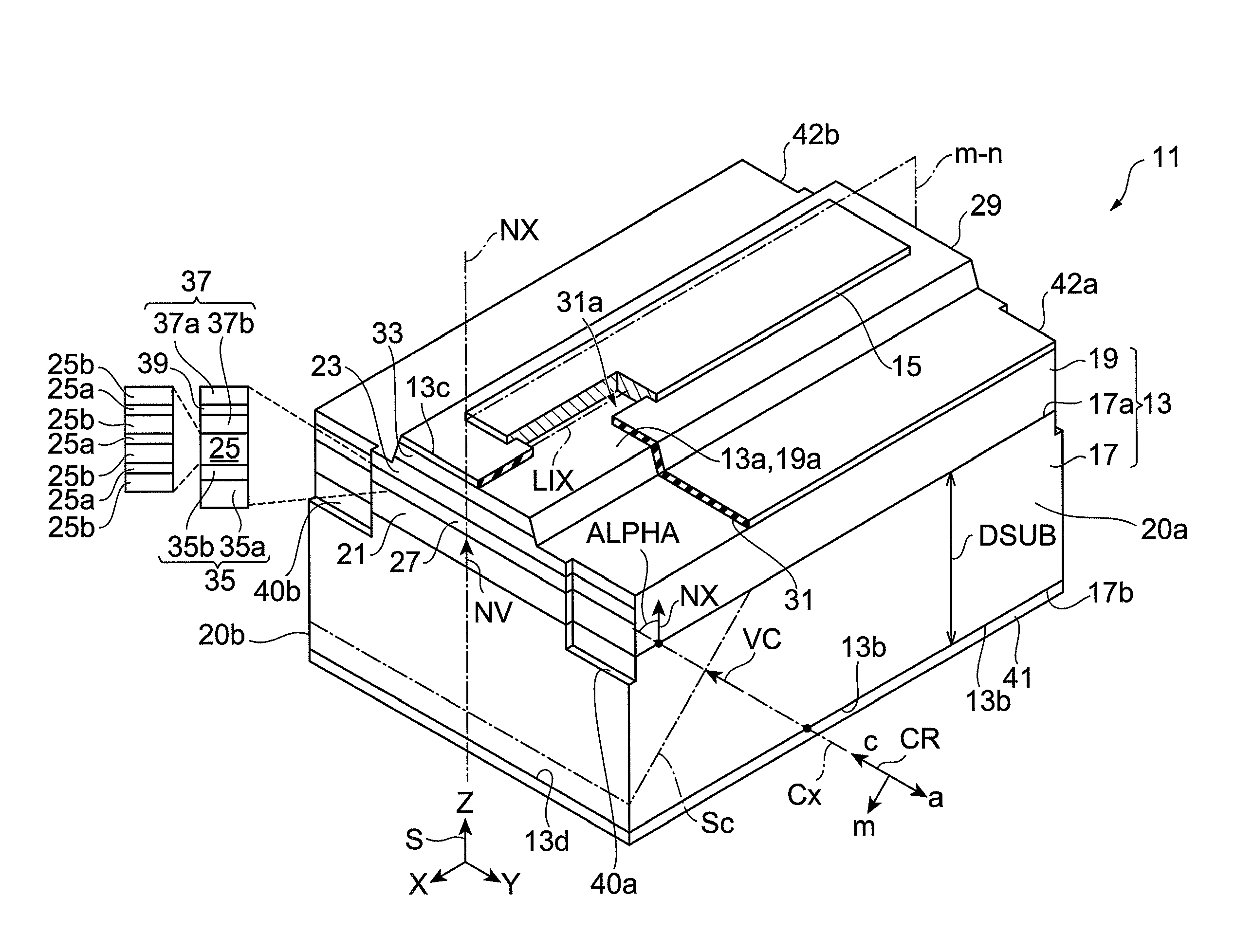
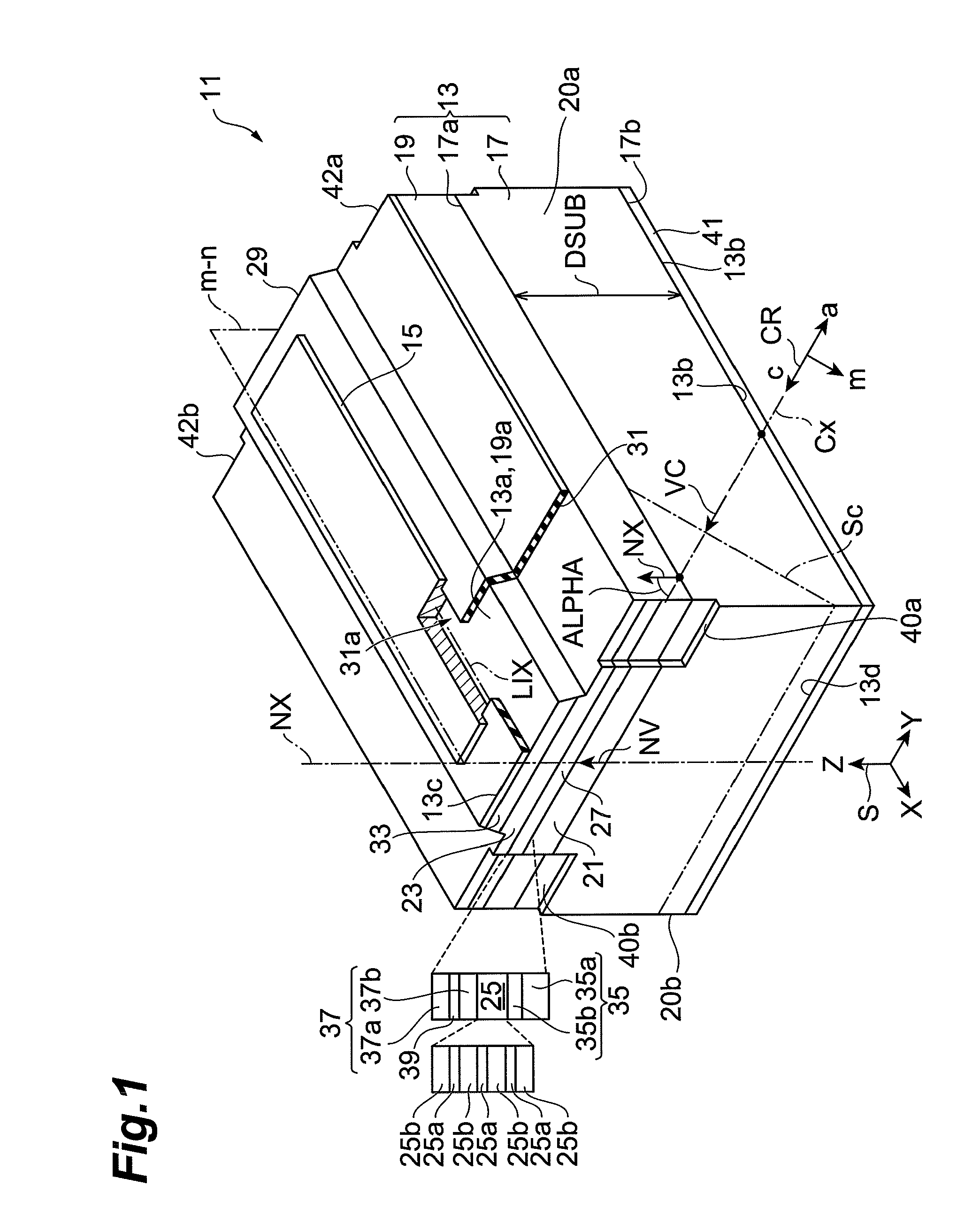
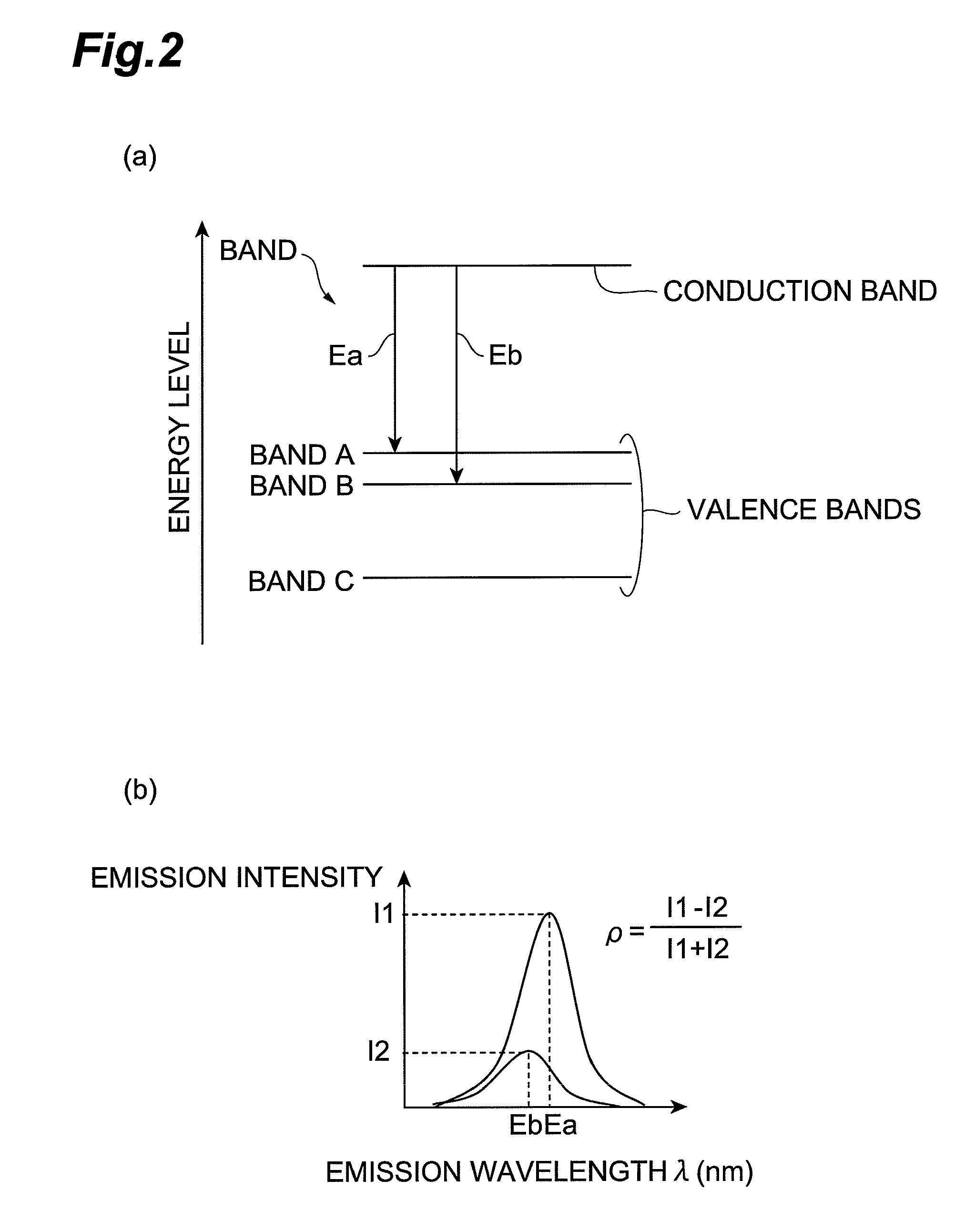
[0010]In the band structure of a GaN-based semiconductor, there are a number of transitions capable of lasing. According to Inventors' knowledge, it is considered that in the III-nitride semiconductor laser device using the semipolar-plane support base the c-axis of which is inclined toward the m-axis, the threshold current can be lowered when the laser waveguide extends along a plane defined by the c-axis and the m-axis. When the laser waveguide extends in this orientation, a lasing mode with the smallest transition energy (difference between conduction band energy and valence band energy) among the possible transitions becomes capable of lasing, and this mode becoming capable of lasing can reduce the threshold current.

Problems solved by technology

However, this orientation of the laser waveguide does not allow use of the conventional cleaved facets such as c-planes, a-planes, or m-planes for the cavity mirrors.
It becomes a heavy burden to derive process conditions for obtaining excellent dry-etched facets in the current technical level.

Method used


Image

  • Method of fabricating group-III nitride semiconductor laser device
  • Method of fabricating group-III nitride semiconductor laser device
  • Method of fabricating group-III nitride semiconductor laser device

Examples


example 1

[0110]A semipolar-plane GaN substrate is prepared and perpendicularity of a fractured face is observed as described below. The substrate used is a {20-21}-plane GaN substrate cut at the angle of 75 degrees toward the m-axis out of a (0001) GaN ingot thickly grown by HVPE. The primary surface of the GaN substrate is mirror-finished and the back surface is in a ground pear-skin state. The thickness of the substrate is 370 μm.

[0111]On the back side in the pear-skin state, a marking line is drawn perpendicularly to the projected direction of the c-axis on the primary surface of the substrate, with a diamond pen and thereafter a substrate product is broken by the press according to the method shown in FIG. 7.

[0112]Part (a) of FIG. 9 is a scanning electron microscope image obtained by observing a fractured face from the a-plane direction, in which the right end face is the fractured face. It is seen that the fractured face has flatness and perpendicularity to the semipolar primary surface...

example 2

[0114]It is found in Example 1 that in the GaN substrate having the semipolar {20-21} plane, the fractured face obtained by drawing the marking line perpendicular to the projected direction of the c-axis on the primary surface of the substrate and pressing the substrate has the flatness and perpendicularity to the primary surface of the substrate. For checking applicability of this fractured face to the laser cavity, a laser diode shown in FIG. 10 is grown by metal-organic vapor phase epitaxy as described below. The raw materials used are trimethyl gallium (TMGa), trimethyl aluminum (TMAl), trimethyl indium (TMIn), ammonia (NH3), and silane (SiH4). A substrate 71 is prepared. The substrate 71 prepared is a GaN substrate cut at an angle in the range of 0 degrees to 90 degrees toward the m-axis out of a (0001) GaN ingot thickly grown by HVPE, with a wafer slicing device, in such a manner that the angle ALPHA of inclination of the c-axis toward the m-axis has a desired off angle in the...

example 3

[0143]In Example 2, the plural epitaxial films for the semiconductor laser are grown on the GaN substrate having the {20-21} plane. The end faces for the optical cavity are formed by the formation of scribed grooves and the press as described above. In order to find candidates for these end faces, plane orientations making an angle near 90 degrees to the (20-21) plane and being different from the a-plane are determined by calculation. The following angles and plane orientations have angles near 90 degrees to the (20-21) plane.

[0144]

Specific plane indexAngle to {20-21} plane(−1016):92.46 degrees;(−1017):90.10 degrees;(−1018):88.29 degrees.

[0145]FIG. 17 is a drawing showing atomic arrangements in the (20-21) plane, (−101-6) plane, and (−1016) plane. FIG. 18 is a drawing showing atomic arrangements in the (20-21) plane, (−101-7) plane, and (−1017) plane. FIG. 19 is a drawing showing atomic arrangements in the (20-21) plane, (−101-8) plane, and (−1018) plane. As shown in FIGS. 17 to 19,...


PUM


Abstract

A method for fabricating a III-nitride semiconductor laser device includes: forming a substrate product having a laser structure; scribing a first surface of the substrate product to form a scribed mark, which extends along a reference line indicative of a direction of the a-axis of the hexagonal III-nitride semiconductor, on the first surface, a scribed mark; mounting the substrate product on a breaking device to support first and second regions of the substrate product by first and second support portions, respectively, of the breaking device; and carrying out breakup of the substrate product by press in alignment with the scribed mark in a third region, without supporting the third region of the substrate product located between the first and second regions, to form another substrate product and a laser bar. First and second end faces of the laser bar form a laser cavity of the III-nitride semiconductor laser device.

Description

BACKGROUND OF THE INVENTION[0001]1. Field of the Invention[0002]The present invention relates to a method for fabricating a Group III-nitride semiconductor laser device.[0003]2. Related Background Art[0004]Non-patent Literature 1 discloses a semiconductor laser made on a c-plane sapphire substrate. The mirror faces of the semiconductor laser are made by dry etching. It shows micrographs of the cavity mirror faces of the laser and describes that the roughness of the end faces is about 50 nm.[0005]Non-patent Literature 2 discloses a semiconductor laser made on a (11-22)-plane GaN substrate. The mirror faces of the semiconductor laser are formed by dry etching.[0006]Non-patent Literature 3 discloses a gallium nitride (GaN)-based semiconductor laser. It proposes generation of laser light polarized in an off direction of the c-axis of the substrate, in order to use m-planes of cleaved facets for the laser cavity. Specifically, this Literature discloses increase of the well thickness on a...

Claims


Application Information

Patent Timeline
Patent Type & Authority Patents(United States)
IPC IPC(8): H01L21/18
CPCH01S5/0202H01S5/3202H01S5/2201H01S5/32341H01S5/2009H01S5/2031H01S5/320275H01S5/3213H01S5/34333
Inventor TAKAGI, SHIMPEIYOSHIZUMI, YUSUKEKATAYAMA, KOJIUENO, MASAKIIKEGAMI, TAKATOSHI
Owner SUMITOMO ELECTRIC IND LTD
Why Eureka
Try Eureka