
Flexible substrate for a semiconductor package, method of manufacturing the same, and semiconductor package including flexible substrate

Active Publication Date: 2012-02-07
SAMSUNG ELECTRONICS CO LTD
View PDF18 Cites 2 Cited by
  • Summary
  • Abstract
  • Description
  • Claims
  • Application Information

AI Technical Summary

Benefits of technology

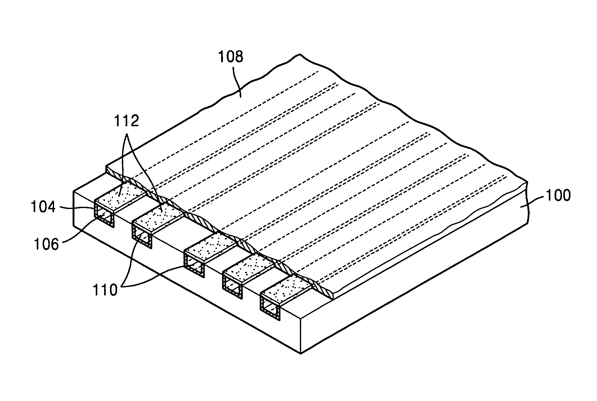
[0013]Exemplary embodiments of the present invention provide a flexible substrate semiconductor package and method for manufacturing the same in which a circuit pattern may be formed in an imprinting process simplifying a semiconductor manufacturing process, increasing productivity and yield, and reducing manufacturing costs.
[0016]In an exemplary embodiment of the present invention, the insulating substrate may be formed of a thermosetting resin or a photo-crosslinkable resin and may be formed of one ore more materials selected from an insulating material group which may include polyimide and polybenzoxazole, which may have higher heat-resistance and durability.
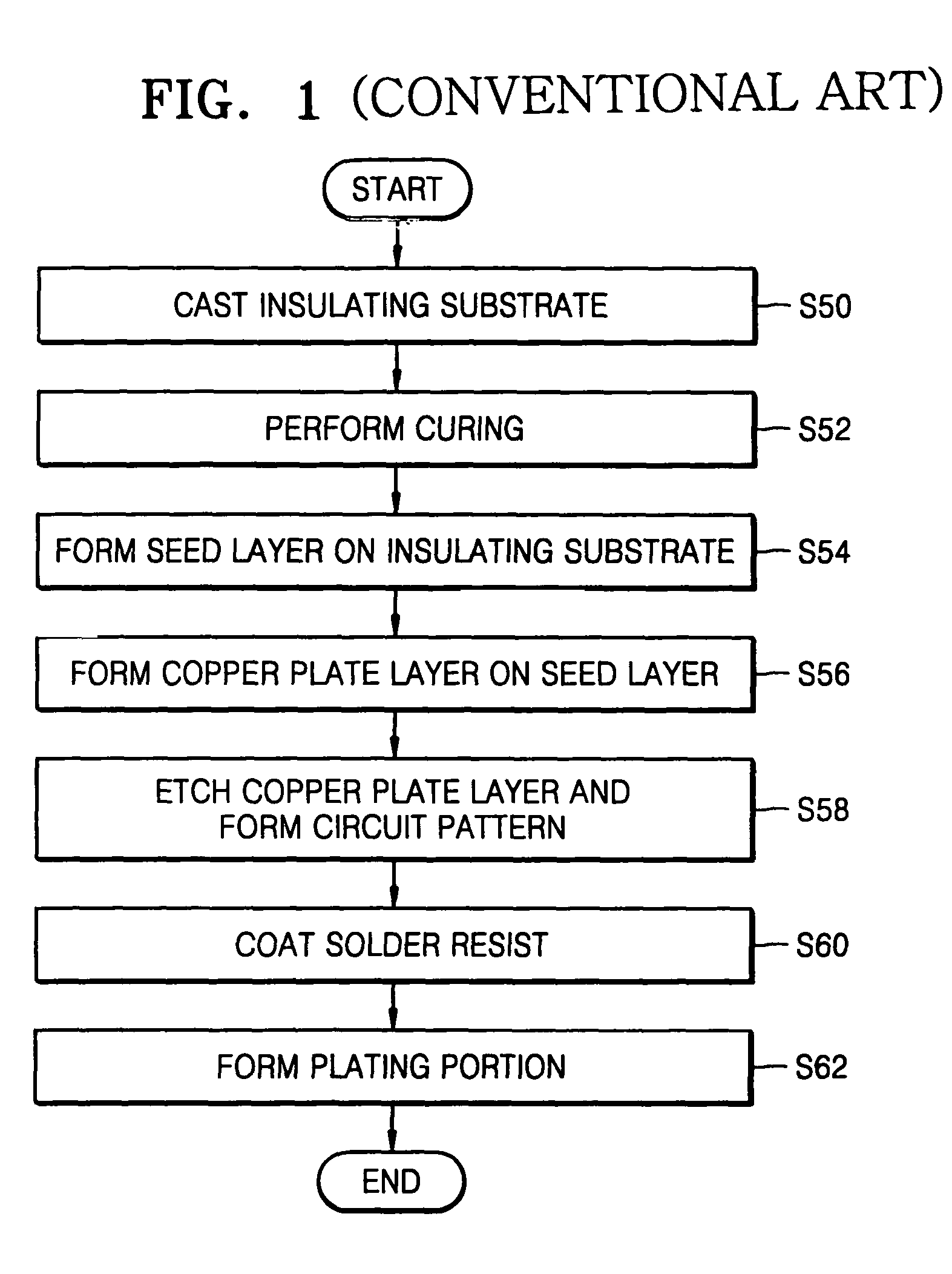
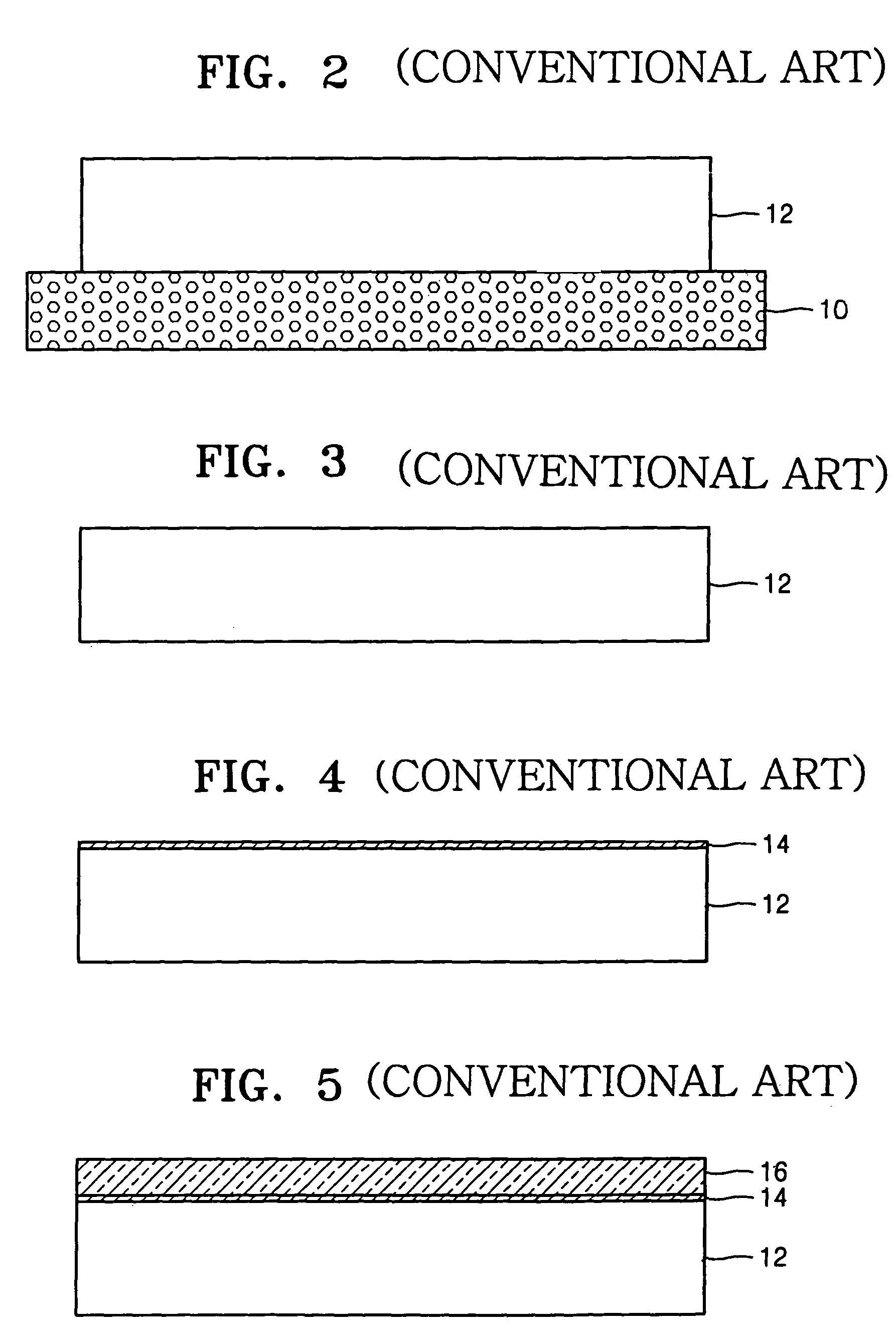
[0019]In an exemplary embodiment of the method of manufacturing, a polymer solution may be coated on a casting vessel, and the polymer solution may be pre-cured. A polymer film, which may be for an insulating substrate may be formed, and an imprinted circuit pattern forming region, which may use a metallic pattern, may be formed in the polymer film. The polymer film, in which the imprinted circuit pattern forming region may be formed, may be cured, which may increase the density of the polymer film. A sprocket hole may be formed in the polymer film, and the polymer film in which the sprocket hole may be formed, may be wound in a reel.
[0020]In an exemplary embodiment of the method of manufacturing, a polymer solution may be coated a first time on a casting vessel, and the polymer solution may be dried and pre-cured. The polymer solution may be coated a second time on the casting vessel, and the polymer solution may be dried. The imprinted circuit pattern region may be formed in the polymer solution using the metallic pattern, the polymer solution may be cured, and a polymer film may be formed, which may increase the density of the polymer film. A sprocket hole may be formed in the polymer film, and the polymer film, in which the sprocket hole may be formed, may be wound in a reel.
[0021]In an exemplary embodiment of the present invention, the forming of the circuit pattern region may comprise pressing the metallic pattern into the polymer film, and baking the polymer film at 200 to 360° C. which may increase a rate of cross-linking in the polymer film.
[0023]In another exemplary embodiment of the present invention, the forming of the circuit pattern region may be performed by inserting a paste which may be formed of a conductive material, into the circuit pattern forming region using a squeeze plate. Exemplary embodiments of the method of manufacturing a flexible substrate for a semiconductor package according to the present invention may not involve a photolithography process using a photoresist, which may reduce manufacturing costs, and / or improve productivity. Further defects that may occur when forming a circuit pattern using a metallic material may be reduced, reliability of the flexible substrate may be improved, and / or a circuit pattern having a finer line width may be formed with improved yield.

Problems solved by technology

Accordingly, a higher yield may not be obtained and / or the semiconductor manufacturing process may be inefficient.

Method used


Image

  • Flexible substrate for a semiconductor package, method of manufacturing the same, and semiconductor package including flexible substrate
  • Flexible substrate for a semiconductor package, method of manufacturing the same, and semiconductor package including flexible substrate
  • Flexible substrate for a semiconductor package, method of manufacturing the same, and semiconductor package including flexible substrate

Examples


Embodiment Construction

[0034]Exemplary embodiments of the present invention will now be described more fully with reference to the attached drawings in which exemplary embodiments of the invention are shown.

[0035]A flexible substrate for a semiconductor package, for example an LCD driving integrated circuit (LDI), according to the exemplary embodiments of the present invention may be used with the broadest meaning and may not be limited to a flexible substrate for a specific semiconductor package such as a chip on film (COF) package.

[0036]In an exemplary embodiment, a flexible substrate may be used in a COF package, however, the flexible substrate may be used in a wafer level package (WLP), ball grid array (BGA) package, or any other package. Further, various changes in a process of forming a circuit pattern forming region on an insulating substrate and in a process of forming a plating portion and a solder resist may be made by those skilled in the art. The contents described in the following embodiments...


PUM

PropertyMeasurementUnit
Temperatureaaaaaaaaaa
Lengthaaaaaaaaaa
Lengthaaaaaaaaaa

Abstract

A flexible substrate used in a semiconductor package, a method of manufacturing the same, and a semiconductor package including the flexible substrate. A circuit pattern forming region is formed in an insulating substrate with a dented shape and a circuit pattern formed of a metallic material is formed in the circuit pattern forming region.

Description

CROSS-REFERENCE TO RELATED APPLICATIONS[0001]This application claims the benefit of priority of Korean Patent Application No. 2003-37859, filed on Jun. 12, 2003, in the Korean Intellectual Property Office, the disclosure of which is incorporated herein in its entirety by reference.FIELD OF THE INVENTION[0002]The present invention relates to a flexible substrate and method for manufacturing the same, and more particularly, to a flexible substrate, method of manufacturing, and a semiconductor used in an LCD driving integrated circuit (LDI) semiconductor package.DESCRIPTION OF THE CONVENTIONAL ART[0003]As semiconductor devices become thinner, smaller, more highly integrated, and / or faster with an increasing number of pins, the use of a flexible substrate with an insulating substrate formed of a flexible material may become more important when mounting semiconductor chips.[0004]In a conventional flexible substrate, a flexible pattern and a lead, which may be connected to the flexible pa...

Claims


Application Information

Patent Timeline
IPC IPC(8): H01L23/12H01L21/48H01L23/498H05K1/00H05K1/11H05K3/04H05K3/06H05K3/10H05K3/12H05K3/24H05K3/28H05K3/38
CPCH01L21/4846H05K3/107H05K3/1258H01L23/4985H01L21/3122Y10T29/49227H01L2224/16H01L2924/01078H01L2924/01079H01L2924/12044H05K1/0393H05K3/045H05K3/06H05K3/243H05K3/28H05K3/388H05K2201/0108H05K2201/0376H05K2201/09036H05K2203/0108H01L23/3107H01L2224/73204H01L2224/16225H01L2224/32225H01L2924/00H01L2924/00014H01L2224/0401H05K1/11
Inventor CHOI, KYOUNG-SEI
Owner SAMSUNG ELECTRONICS CO LTD
Learn More