MECS dialyzer

a dialyzer and micro-technology technology, applied in the field of hemodialysis, can solve the problems of reducing the efficiency of mass transfer on the dialysate side, hollow fiber dialyzers have a mal-distribution of dialysate flow, and the technology has not changed significantly, so as to accelerate the mass transfer in dialysis applications

Active Publication Date: 2012-03-06
OUTSET MEDICAL
View PDF59 Cites 27 Cited by
  • Summary
  • Abstract
  • Description
  • Claims
  • Application Information

AI Technical Summary

Benefits of technology

[0026]The present invention is related to hemodialysis, and more particularly, to a dialyzer with improved efficiency of mass transfer across a dialysis membrane utilizing microchannel separation provided in accordance with embodiments of the present invention. In accordance with an embodiment, a dialyzer is provided comprising a plurality of semipermeable membrane sheets and a plurality of flow separators. The membrane sheets and flow separators are arranged in alternating configuration and coupled into a laminae stack defining a plurality of parallel microchannel layers. Each microchannel layer comprises a plurality of first microchannels and a plurality of second microchannels. The first and second microchannels of each microchannel layer are in fluid communication with each other via one of the plurality of membrane sheets therebetween.
[0041]Dialyzers made in accordance with the present invention provide embedded highly-parallel or perpendicular arrays of microchannels capable of accelerating the mass transfer in dialysis applications. Small characteristic sizes provided by the microchannels provide the benefits of large surface-to-volume ratios, laminar flow conditions and the opportunity of operating at elevated pressures.
[0042]Extremely high rates of mass transfer are obtainable in microchannels. The MECS dialyzer which incorporates microchannel geometry and micro-lamination manufacturing technologies radically reduces the characteristic or residence time required for mass transfer in a dialysis application. The microtechnology-based design maintains micro-scale dimensions evenly on both sides of the membrane. In an embodiment in accordance with the present invention, a microtechnology-based MECS dialyzer is provided with dialysate flow channel dimensions of 100 microns. Compared to a conventional dialyzer with hollow fibers, this geometry reduces the size of a dialyzer by a factor of 10 to 100 for the same operating parameters.
[0043]A major benefit of the MECS dialyzer in accordance with the present invention is the ability to optimize the dialysate flow so as to approach 100% utilization. The MECS dialyzer in accordance with embodiments of the present invention, uses a structured flow of dialysate through fixed-width microchannels. The spacing of the microchannels is predetermined for effective utilization of the dialysate used to clean the blood. Less dialysate solute reduces the dialysis machine size.
[0044]Additionally, the structured flow path minimizes areas of stagnant flow, eliminates shunt flows, and ensures maximum utilization of all areas of membrane exposed to the dialysate flow. This greatly improves solute clearance and allows for the dialyzer to have less surface area for a given performance requirement as compared with currently available hollow fiber dialyzers. The reduced membrane length and surface area reduces the pressure on the blood leading to a reduction in hemolysis and reduction in the amount of blood within the circuit that is outside the patient during treatment.

Problems solved by technology

Though the hollow fiber dialyzers of today are a bit more efficient, the technology has not changed significantly since this time.
The hollow fiber dialyzer has a mal-distribution of dialysate flow due to uneven and inconsistent spacing between individual fibers.
Areas with stagnant flow as well as areas with developed shunt flow dramatically reduce the efficiency of the mass transfer on the dialysate side.
Improvement of diffusion, and hence improved dialysate usage efficiency is limited due to the inherent physical character of the hollow-fiber dialyzers.
A relatively large quantity of dialysate solution is used because the flow of dialysate is haphazard around the fibers.

Method used


Image

  • MECS dialyzer
  • MECS dialyzer
  • MECS dialyzer

Examples


Embodiment Construction

[0045]Reference will now be made to embodiments illustrated in the drawings and specific language which will be used to describe the same. It will nevertheless be understood that no limitation of the scope of the invention is thereby intended, such alterations and further modifications in the illustrated devices, as such further applications of the principles of the invention as illustrated therein as being contemplated as would normally occur to one skilled in the art to which the invention relates.

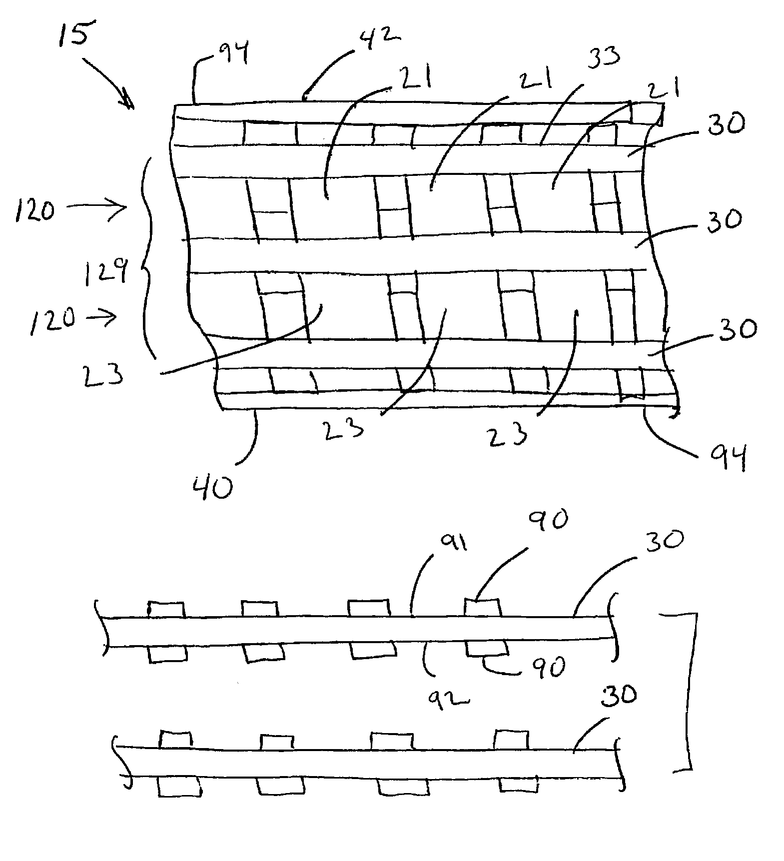
[0046]The term “microchannel” refers to a channel having at least one internal dimension of width or height of up to about 1000 microns.

[0047]The term “non-turbulent” refers to the flow of a fluid through a microchannel that is laminar or in transition. The Reynolds Number for the flow of the fluid through the microchannel may be up to about 4000. The Reynolds Number used herein is calculated using the hydraulic diameter which is based on the actual shape of the microchannel.

[0048]The te...


PUM


Abstract

The present invention is related to hemodialysis, and more particularly, to a dialyser with improved efficiency of mass transfer across a dialysis membrane utilizing microchannel separation provided in accordance with embodiments of the present invention. In accordance with an embodiment, a dialyzer is provided comprising a plurality of semipermeable membrane sheets and a plurality of flow separators. The membrane sheets and flow are arranged in alternating configuration and coupled into a laminae stack defining a plurality of parallel microchannel layers. Each microchannel layer comprises a plurality of first microchannels and a plurality of second microchannels. The first and second microchannels of each microchannel layer are in fluid communication with each other via one of the plurality of membrane sheets therebetween. The MECS dialyzer is characterized as having a high surface to volume ratio and a high mass transfer coefficient.

Description

RELATED APPLICATIONS[0001]This is a non-provisional application claiming benefit under 35 USC §119(e) to Provisional application No. 60 / 616,757, filed on Oct. 6, 2004, which is in its entirety incorporated herewith by referenceFIELD OF THE INVENTION[0002]The present invention is related to hemodialysis, and more particularly, to methods and apparatus for a microtechnology-based dialyzer.BACKGROUND[0003]Chronic dialysis has been performed on patients with kidney failure since the early 1960's. The dialyzers or “artificial kidneys” that made this possible were a result of a technical evolution that began in the 1930's and 1940's. A dialyzer is a device for cleansing blood through hemodialysis by a process of diffusion and convection of waste products, dissolved solutes and fluid from the blood across a semi-permeable membrane into a dialysis solution known as dialysate. A dialyzer system is an assembly comprising the dialyzer and associated equipment to support the dialyzer, such as p...

Claims


Application Information

Patent Timeline
Patent Type & Authority Patents(United States)
IPC IPC(8): B01D61/28B01D61/24
CPCA61M1/16B01D61/28B01D63/081B01D63/082B01D2313/08B01D2313/14A61M2205/0244A61M1/1621B01D63/088
Inventor BROWNING, DAVID M.CURTIS, JAMES R.JOVANOVIC, GORAN NADEZDAPAUL, BRIAN KEVINATRE, SUNDAR
Owner OUTSET MEDICAL
Why Eureka
Try Eureka