Air-cooled plug part for an optical waveguide

a technology of air cooling and optical waveguides, which is applied in the direction of optics, optical light guides, instruments, etc., can solve the problems of maintaining leakage tightness and vapor bubbles, and achieve the effect of reducing the operating temperature range of the involved optics and small air heat capacity

Inactive Publication Date: 2012-03-20
BERGER ROLAND
View PDF11 Cites 5 Cited by
  • Summary
  • Abstract
  • Description
  • Claims
  • Application Information

AI Technical Summary

Benefits of technology

[0008]These problems which are known in the transmission of laser energy have lead to the consideration of using air or some other gas as cooling medium instead of water. Air has the advantage that the phenomenon of the thermal shock described above will not occur, the considerably smaller heat capacity of air proving to be of advantage here. In comparison to a water-assisted cooling, cooling with air allows the operating temperature range of the involved optics to be much larger; it may reach as far as 300° C. to 400° C., for instance. A cooling with liquid air or liquid gases is envisaged, too. Hereby, the temperature range of the cooling medium is extended and may start at −40° C. and less, for instance. In the context of comprehensive preliminary tests it has also been shown that the removal of heat loss from the optical waveguide can also be readily accomplished with air. This is due to the circumstance that the mass to be cooled is relatively small.

Problems solved by technology

In practice it has been shown to be a problem that despite a water-assisted cooling the surface temperature of an optical waveguide may rise to more than 100° C., necessarily resulting in vapor bubbles.
A further problem is to maintain the leak-tightness of the water circulation against the background of thermal fluctuations.
With such thermal fluctuations the differing coefficients of linear expansion of the materials (common matching glass / metal) are the reason for such problems in terms of leak-tightness.
These problems which are known in the transmission of laser energy have lead to the consideration of using air or some other gas as cooling medium instead of water.

Method used


Image

  • Air-cooled plug part for an optical waveguide
  • Air-cooled plug part for an optical waveguide
  • Air-cooled plug part for an optical waveguide

Examples


Embodiment Construction

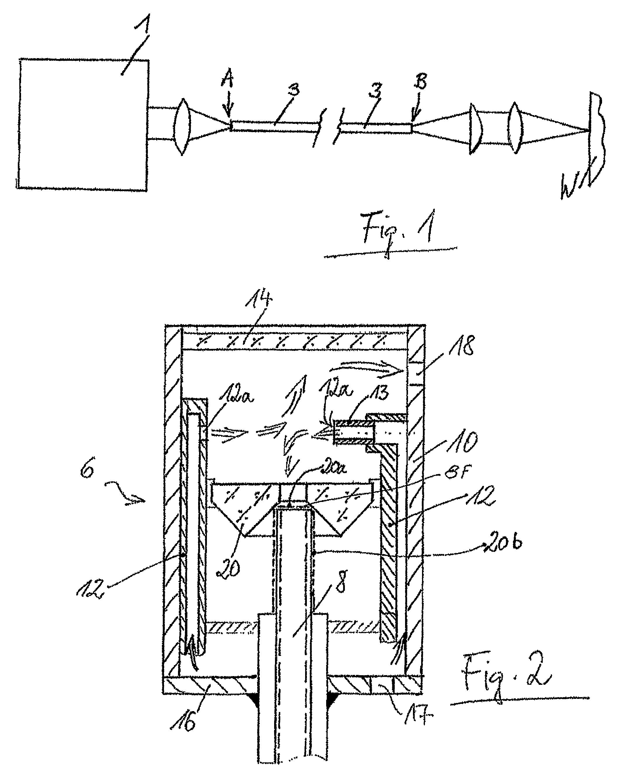
[0012]FIG. 1 shows in a greatly schematized form an exemplary transmission path is for a laser beam. A laser source 1 is schematically shown on the left side of FIG. 1; such source may be a YAG laser, for example, generating laser radiation in the range up to 6 kW and more. This radiation is guided via a focusing lens to an optical waveguide 3 in order to be coupled into the latter at an area designated with A. The optical waveguide has the function to guide the laser beam to a processing station along routes which often may have considerable lengths of up to 80 m; at the processing station the beam will be used for cutting, welding, marking, ablating, perforating etc. At an area B the laser beam exits the optical waveguide, runs through a collimation lens, a second focusing lens and finally arrives at the work piece W which is to be processed.

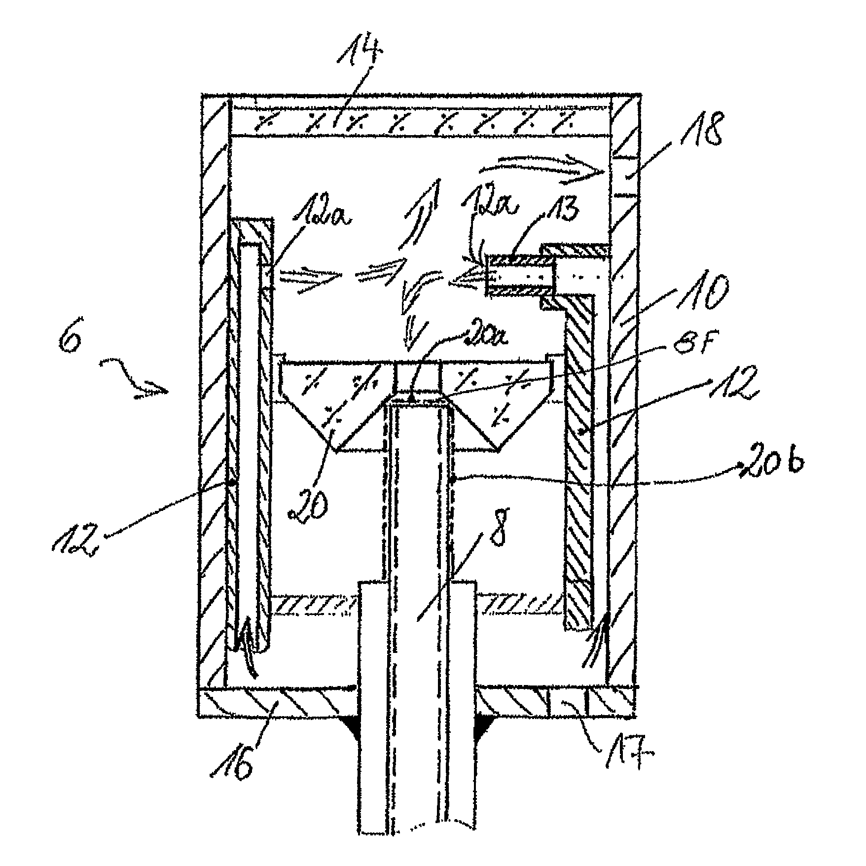
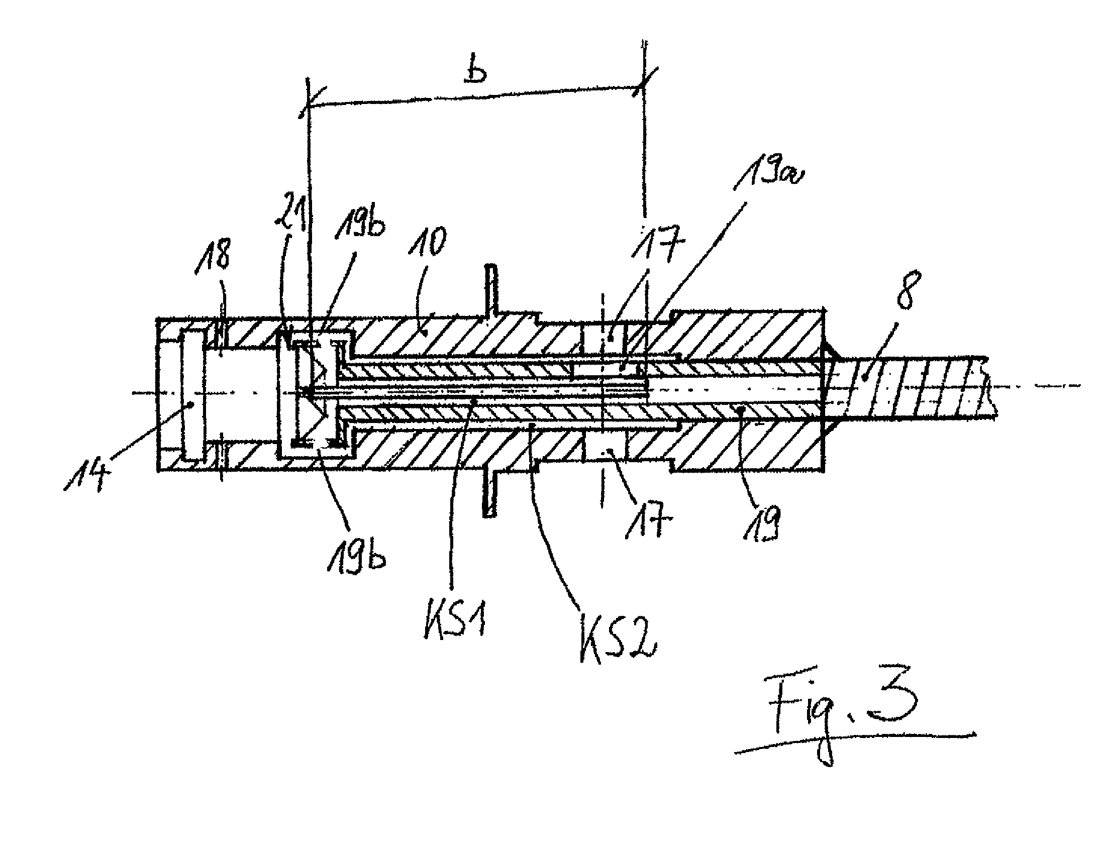
[0013]At the areas designated with A and B the plug part of the invention may be employed, although it is possible here for functional reason...


PUM


Abstract

A plug part for an optical waveguide (8), comprising an essentially cylindrical housing (10), at least one inlet opening (17) and at least one outlet opening (18) for a cooling medium, and a cooling collar (12) which is disposed inside the housing (10) and cools an optical waveguide (8) located in the housing (10) at least along one section (b) of the length thereof. The disclosed plug part includes a protective glass (14), across at least almost the entire internal surface of which the cooling medium flows, is provided at one end of the housing, the front of the optical waveguide (8) also being impinged upon by the cooling medium. An embodiment of a plug part for an optical waveguide (8) includes an inserted tube element (19) which divides a cooling medium flow that circulates through housing (10) into a first and a second individual flow channel (KS1, KS2).

Description

BACKGROUND[0001]1. Field of the Invention[0002]The present invention relates to an air-cooled plug part for an optical waveguide (LWL) which is particularly suited for the transmission of laser radiation.[0003]2. Related Art[0004]In transmitting laser radiation from a beam source to a processing station, a beam energy exists which typically lies in the range from a few milliwatt to several kilowatt. This energy is guided along an optical waveguide which generally has a diameter from 200 to 600 μm, in exceptional cases up to approximately 1.2 mm. An optical waveguide essentially consists of a core fiber (core) and a surrounding covering (cladding) which both are made of quartz glass. The cladding is adjoined by a silicone mass, and the outermost layer is often a plastic sheathing. The beam normally runs in the core fiber; if the radiation is not situated centrally in the core, an input of energy into the cladding will occur. The warming which is due to the high transmitted energy is ...

Claims


Application Information

Patent Timeline
Patent Type & Authority Patents(United States)
IPC IPC(8): G02B6/36G02B6/00
CPCG02B6/3813G02B6/3814G02B6/4296
Inventor BERGER, ROLAND
Owner BERGER ROLAND
Why Eureka
Try Eureka