Forged copper burner enclosure

a technology of forged copper and burner enclosure, which is applied in the direction of furnaces, combustion types, lighting and heating apparatus, etc., can solve the problems of cumbersome reaction zone materials, heat damage to burners, and not being useful to reach or be positioned, so as to improve the life of the burner enclosure, eliminate stalling and hot spots, and eliminate turbulence in critical areas

Inactive Publication Date: 2012-03-27
NUCORE TECH
View PDF31 Cites 10 Cited by
  • Summary
  • Abstract
  • Description
  • Claims
  • Application Information

AI Technical Summary

Benefits of technology

[0014]In each arcuate compartment is sealably mounted a header plate which is shaped to conform to the arcuate compartment periphery. Further, each header plate has four evenly spaced apertures that communicate with four tubes that are sealably mounted and aligned with respective blind holes. The tubes extend outwardly from the bottom of the header plate. The tubes are shorter in length than the depth of each of the deep drilled blind holes machined into the burner enclosure. Therefore, each hole has a chamber between the end of the tube and the bottom wall of the blind hole so that water flowing down each tube can flow through the chamber and back up towards the header plate between the outside diameter of the tube and the insider diameter of the wall of the deep drilled blind hole in the burner enclosure. Since the deep drilled blind holes are considerably larger than the outside diameter of the tube mounted in each hole a continuous flow path of coolant is established for each tube and deep drilled blind hole combination. The flow path allows cooling water to flow down inside the tube into the chamber at the bottom of each hole where the coolant is further directed to flow upward between the outer wall of the tube and the inner wall of the hole.
[0016]Therefore, it is an object of the invention to provide a burner enclosure for an oxygen lance or burner which is durable and not prone to erosion and cracking or weld failures.
[0017]It is yet a further object of the invention to provide a burner enclosure for an oxygen lance or burner which provides better strength and heat transfer.
[0019]It is yet a further object of the invention to provide a burner enclosure for an oxygen lance or burner which incorporates machined water channels for uniform coolant to flow through the burner enclosure thereby eliminating stalling and hot spots and increasing the life of the burner enclosure.
[0020]It is still a further object of the invention to maintain a uniform cooling water flow through the burner enclosure in order to eliminate stalling and turbulence in critical areas.
[0021]It is still a further object of the invention to maintain coolant flow at a high velocity to prevent any solid deposits from clogging cooling passages.

Problems solved by technology

Further, overhead water cooled lances such as disclosed by Metz, et al., while being able to be submerged directly into the molten bath to efficiently place gases and materials in a reaction zone are cumbersome and must be lowered vertically through the top of a steel making vessel.
Because of their weight and size, they are not very useful to reach or be positioned for effective injection in an electric arc furnace.
These early problems evolved into the introduction of fixed position burners / injectors that protrude out into the furnace.
Further, such action causes splashing of the liquid which can result in heat damage to the burner.
Since most burners are made from copper castings or fabricated copper / steel weldments, the burner design itself is considerably more complicated to accommodate the coolant passages.
Also, such mold design issues can cause stalling of the coolant flow in reduced service life due to wear of the casting.
Also, as stated above, such burners are prone to damage as a result of the hot melt splashing on the burner tip in the harsh environment.
However, with a burner recessed within a cavity, combustion may, and usually does occur within the cavity thus generating heat close to the burner surface and again increasing heat to the burner which may cause corrosion of the castings and reduce its efficiency.
Further, if the burner is a weldment, such are prone to weld failures, which may cause water to leak into the furnace in the case of a water cooled burner.
Also, recessing the burner in the furnace wall increases the distance to the molten metal, reducing its efficiency

Method used


Image

  • Forged copper burner enclosure
  • Forged copper burner enclosure
  • Forged copper burner enclosure

Examples


Embodiment Construction

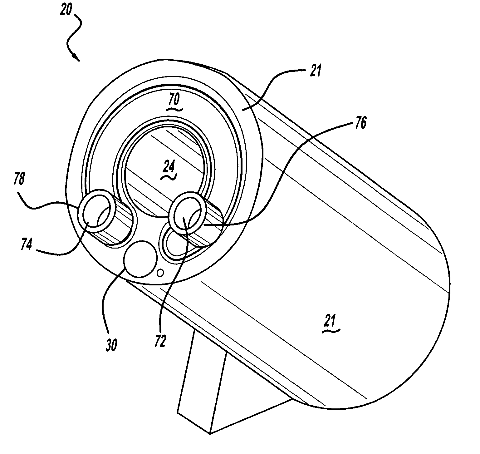
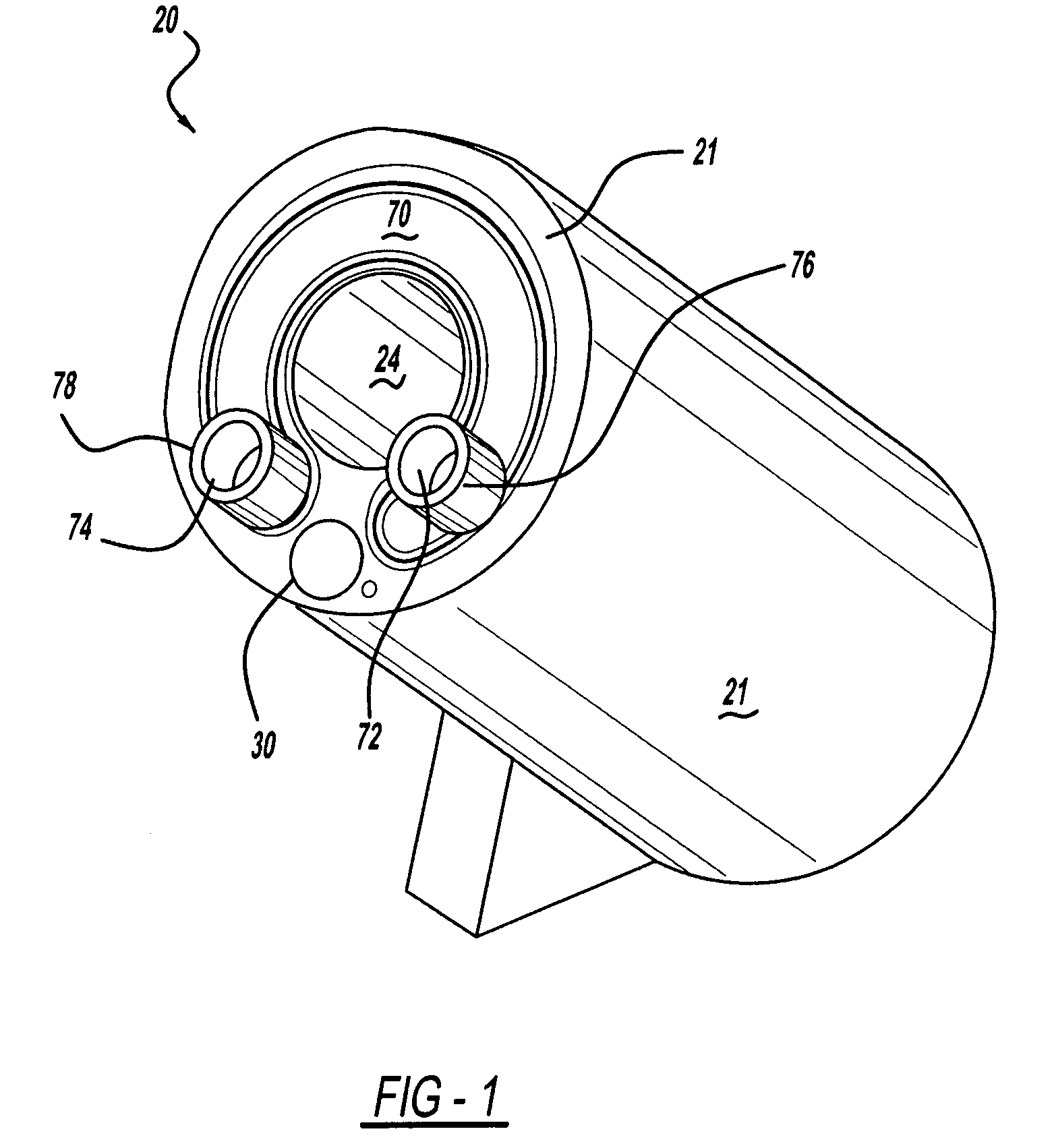
[0033]In FIG. 1 (as assembled) and FIG. 5 (exploded view), there is shown a forged burner enclosure 20 in perspective consisting of a burner housing 21 with three concentrically spaced header and tube assemblies 40 which mount into deep drilled blind holes 28 at the top of arcuate compartments 26a, 26b, and 26c in the burner housing 21; and a cover plate 70 for covering the header and tube assemblies 40 containing the coolant inlet port 72 and coolant outlet port 74 with their respective inlet 76 and outlet 78 coolant fittings welded concentrically to their respective ports. The complete assembly is accomplished by welding each of the three header and tube assemblies 40 in place after they are inserted into the burner housing 21 and further welding the cover plate 70 at the top of the arcuate counterbore 25 provided in the burner housing 21 as will be described hereinafter. After assembly, the forged burner enclosure 20 is mounted in the sidewall of the shell of an electric arc furn...


PUM

PropertyMeasurementUnit
angleaaaaaaaaaa
diameteraaaaaaaaaa
life timeaaaaaaaaaa

Abstract

A forged copper burner enclosure capable of being mounted within the side wall of a steel melting furnace for the purpose of providing an improved cooling characteristic to a burner lance. The burner enclosure is provided with a central passage adapted to receive a burner lance for injecting oxygen into the batch of molten metal of an electric arc furnace. The forged burner enclosure is positioned such that only a solid forged copper face is on the furnace side when installed. The burner enclosure has an optional through hole which can be used for the purpose of treating the metal melt with particulate supply ranging from slag forming materials to metallurgical materials. The burner enclosure further has a number of coolant holes and tubes which provide a unique bidirectional flow of cooling fluid through each hole and increases cooling fluid velocity while reducing stalling and hot spots of the cooling fluid thereby providing better heat transfer and physical characteristics over cast or weld-assembled burner enclosures.

Description

CROSS-REFERENCE TO RELATED APPLICATIONS[0001]Not applicable.BACKGROUND OF THE INVENTION[0002]1. Field of the Invention[0003]The invention generally relates to an improved liquid cooled forged burner enclosure for holding a burner or lance to inject oxygen into an electric arc furnace during the steel making process and more particularly to a cooling arrangement for a burner enclosure surrounding a central duct for the supply of oxygen which is blown into the bath of molten steel.[0004]2. Description of the Prior Art[0005]In an effort to increase efficiency of the steel producing process and reduce the overall manufacturing costs, steel producers have, for the past few years, evolved to using oxidizing gases, preferably oxygen in the melting, refining, and processing steps of making steel in an electric arc furnace. Oxygen is used at different points in the melting and refining process in an electric arc furnace. Initially, it may be used to add heat during the pre-heating phase of a...

Claims


Application Information

Patent Timeline
Patent Type & Authority Patents(United States)
IPC IPC(8): C21B7/02
CPCC21C5/5217F23D14/78F27B3/205F27D99/0033Y02P10/20
Inventor GLASS, JOSHUA W.
Owner NUCORE TECH
Why Eureka
Try Eureka