Supercharge Your Innovation With Domain-Expert AI Agents!

Transceiver for single ended communication with low EMI

a transceiver and low emi technology, applied in the field of launch signals, can solve the problems of differential cable skew, high cost of differential cable and connector, and wave coupling in the cable between differential and common mode, so as to reduce the emi radiation and effectively cancel the common mode component

Active Publication Date: 2012-04-24
EQCOLOGIC
View PDF14 Cites 3 Cited by
  • Summary
  • Abstract
  • Description
  • Claims
  • Application Information

AI Technical Summary

Benefits of technology

This solution significantly reduces EMI emissions by canceling common mode currents and achieving a balanced PCB layout, improving EMI emission by up to 20 dB compared to prior art solutions, while maintaining low radiation and immunity to bulk current injection.

Problems solved by technology

Many examples of commercialized technologies exist, like, USB (Universal Serial Bus), HDMI (High Definition Multimedia Interface), DisplayPort, Serial ATA (Advanced Technology Attachment), etc. . . . However, differential connectors and cables are more expensive than single ended coaxial cables and connectors.
Furthermore, at high bit rate, differential cables often generate intra-pair skew.
This leads to wave coupling in the cable between differential and common modes, and to final destruction of the transmitted signals.
Skew compensation circuits can only effectively compensate very limited skew at receiver's end due to the destructive effect of the coupling.
The higher relative uncertainty on the characteristic impedance makes a differential cable a less attractive candidate for bidirectional communication.
At high speed, this type of system is highly unbalanced, leading to unwanted electromagnetic radiation, even when the transmit system is in a shielded box.
These applications are further low demanding on EMC levels.
For consumer and certainly for automotive applications the EMC specifications are more difficult to reach.
When the chip also serves as a receiver for high speed signals, it can further be the case that there is frequency dependent signal loss in the coaxial cable.
The difficulty here is that the received high frequency components may become very small with respect to the initial launched signal, and by being small it can easily become a victim of injected bulk current.
The latter can be a result of electromagnetic interference applied close to the receive end of the coaxial cable.

Method used


Image

  • Transceiver for single ended communication with low EMI
  • Transceiver for single ended communication with low EMI
  • Transceiver for single ended communication with low EMI

Examples


second embodiment

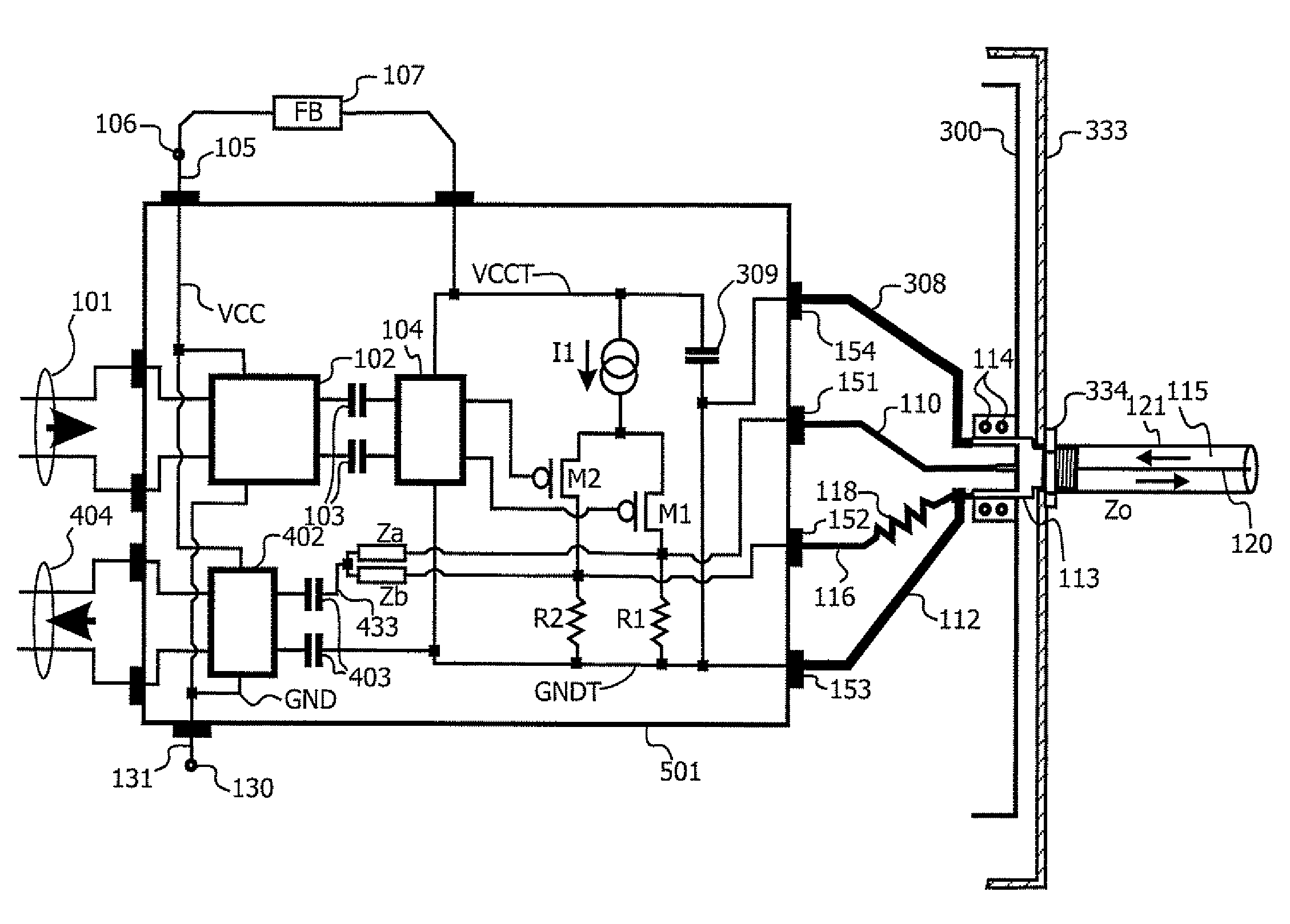
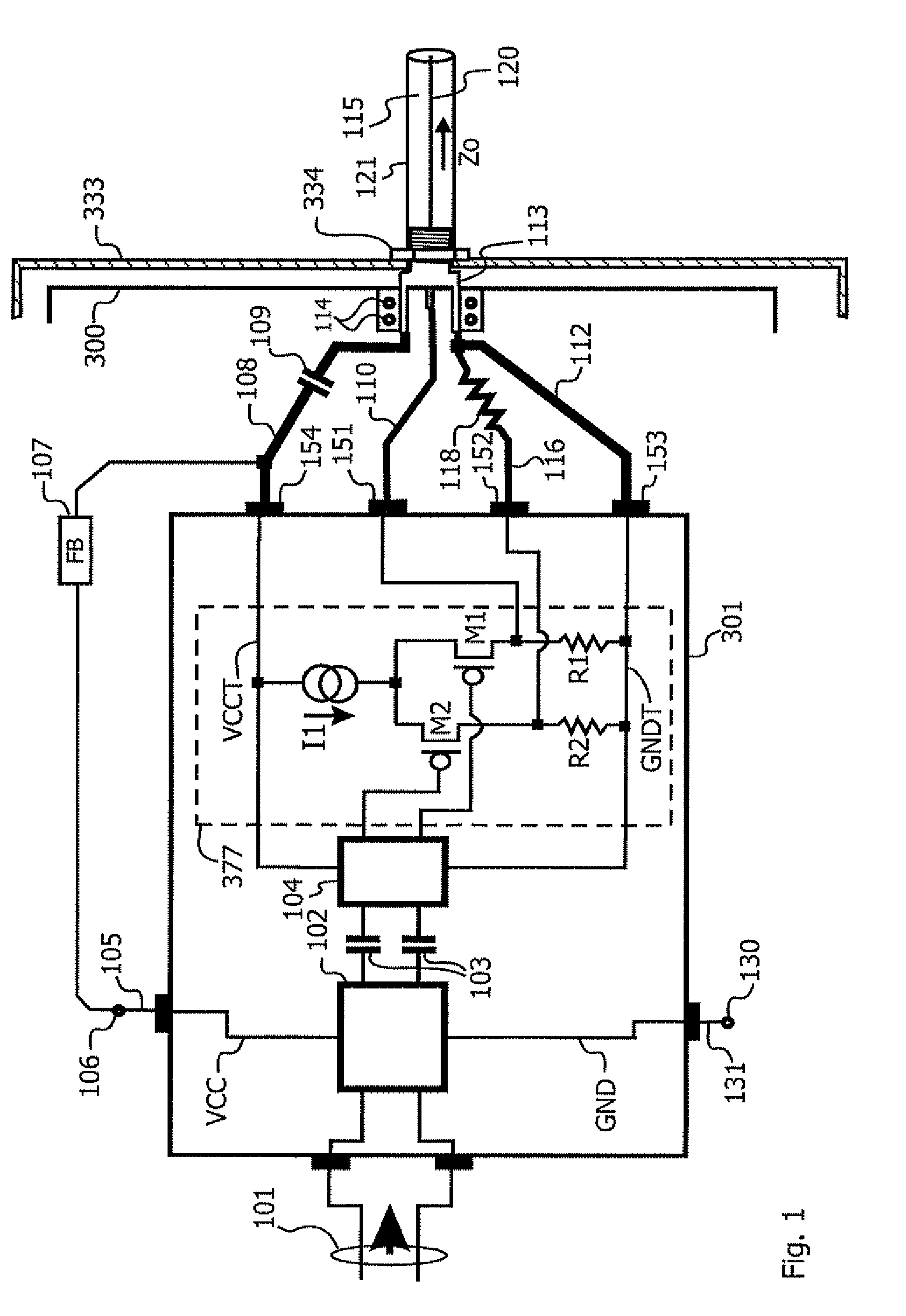
[0057]The same principle, though with just a little different implementation according to the present invention is presented in FIG. 3. The decoupling capacitor 309 is now inside the transmitter chip 401, and the inverse of the common mode signal is transmitted out of the transmitter chip 401 through transmit ground GNDT only, in FIG. 3, through first wire 112. In this case all of the inverse common mode current will flow through the first wire 112 towards the shield pin of the coax connector 113.

[0058]It is also possible with the implementation of FIG. 3 (however, not illustrated), like in the implementation of FIG. 4, that a second wire 308 carries part of the inverse common mode signal towards the coax connector's shield pin.

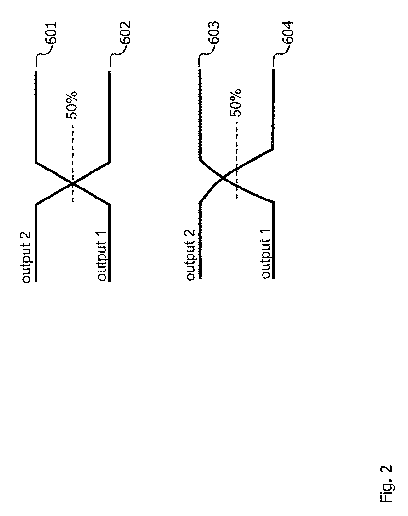
[0059]When the pins of first wire 308, second wire 112, first transmission line 110, and second transmission line 116 are close to each other, like in surface mount technology packages such as e.g. QFN packages, it is suggested to keep the system symmetric fo...

third embodiment

[0062]FIG. 4 shows an implementation according to the present invention that can emit and receive signals over the one attached coaxial cable 115 in full duplex mode, and that shows good immunity to bulk current injection. In this way a bidirectional splitter is obtained with good EMI properties.

[0063]With regard to the emission of the signal, i.e. driving the coaxial cable 115, this is as explained before, and only briefly set out here again. A differential signal 101 is received by a first receiver 102, which receives and terminates the incoming differential signal 101, and preconditions it before transmitting it to a pre-driver 104, through feed-through capacitors 103. The pre-driver 104 drives an output driver stage, for example the gates of output driving transistors M1 and M2 of an output driver stage. The output of the output driving stage, for example the drain voltages of the output driving transistors M1 and M2 are going off-chip, through first and second transmission line...


PUM


Abstract

A cable driver (301) for driving a single ended transmission medium such as a coaxial cable (115) comprising a core (120) and a shield (121) comprises a differential driver (104, 377) comprising a first output (151) for putting a first signal to the core (120) of the single ended transmission medium (115), a second output (152) for putting a second signal to the shield (121) of the single ended transmission medium (115) through a termination resistor (118) having an impedance close to the characteristic impedance (Z0) of the single ended transmission medium (115), and a third output (153) for putting a transmit ground supply signal (GNDT), local to the differential driver, to the shield (121) of the single ended transmission medium (115) through a first high frequency low impedance path (112). In use, the current through the third output (153) will be substantially the inverse of the common mode current through the first and second outputs (151, 152). Hence both the common mode current and its inverse are provided to the single ended transmission medium (115). They cancel each other out and thus advantageously low EMI emissions occur.

Description

FIELD OF THE INVENTION[0001]The present invention relates to launching signals into a single ended coaxial cable in a way that the system will show good EMI (Electro Magnetic Interference) properties. The goal is to achieve low radiation and, furthermore in the case of bidirectional communication, to also achieve good immunity to bulk current injection.BACKGROUND OF THE INVENTION[0002]At present, most high speed (1 Gbps or more) electrical communication over cables is done through differential cables. Differential communication is considered as the best way to achieve sufficient Electro Magnetic Compatibility (EMC), being low radiative emissions at the transmit side and good bulk current immunity at the receive side. Many examples of commercialized technologies exist, like, USB (Universal Serial Bus), HDMI (High Definition Multimedia Interface), DisplayPort, Serial ATA (Advanced Technology Attachment), etc. . . . However, differential connectors and cables are more expensive than si...

Claims


Application Information

Patent Timeline
Patent Type & Authority Patents(United States)
IPC IPC(8): H03K17/16H04B3/28
CPCH03K17/162H03K19/018564H04L25/028
Inventor VAN DEN BRANDE, KOENKUIJK, MAARTEN
Owner EQCOLOGIC
Features
  • R&D
  • Intellectual Property
  • Life Sciences
  • Materials
  • Tech Scout
  • Unparalleled Data Quality
  • Higher Quality Content
  • 60% Fewer Hallucinations
Learn More