Mixed-
signal design content and design complexity is also growing concurrently with the growth in the overall number of mixed-signal designs.
However, current approaches to addressing mixed-signal simulation fall short of mixed-signal analysis and
verification requirements.
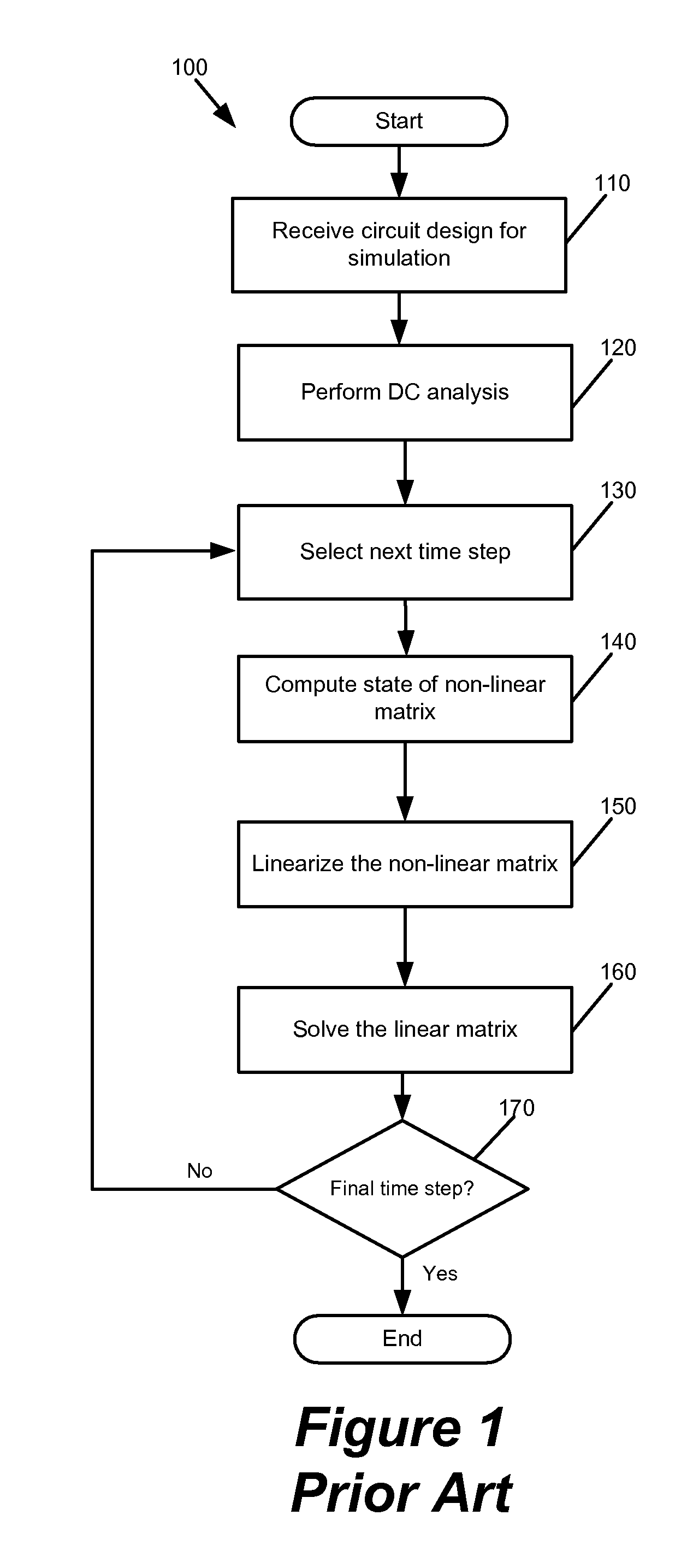
The following techniques have been used in the past, but are no longer adequate: (1) Simulation Program with
Integrated Circuit Emphasis (SPICE) simulation using
sparse matrix solvers, (2) FastSpice simulation using multi-rate algorithms, and (3) a
hybrid approach.
This puts a practical limit on simulation capacity using this approach.
While these products have delivered moderate (e.g., 5-10×) increase in simulation speeds and modest improvement in overall capacity, they fall short of adequately meeting the challenges of large mixed-signal designs.
However, these simulations suffer from accuracy degradation because of a manual setting of accuracy-tolerance, a fundamental reliance on
macro-models to approximately represent circuit behavior, a failure to adhere to Kirchhoff's Current Law (KCL) and Kirchhoff's
Voltage Law (KVL), and a dependence on event-based simulation.
Not understanding these settings properly can result in invalid results.
Additionally, these simulators can only produce accuracy up to 5% of SPICE.
Also, by not solving Kirchhoff's Current Law (KCL) and Kirchhoff's
Voltage Law (KVL), the simulators do not adhere to the fundamental circuit simulation accuracy requirement of
charge conservation.
Lastly, the dependence on event-based simulation further detrimentally affects accuracy of the simulation as
event propagation across partition boundaries is only triggered when there is significant change in
voltage.
The problem with this approach is that designers are required to pre judge and hence bias the simulation, which can result in
design error escapes.
These errors are especially insidious at the digital-analog interfaces.
This approach runs counter to simulation requirements which are becoming increasingly more stringent to address the growth in size, complexity, and performance of mixed-signal designs and adds risk to the critical
design analysis and
verification process.
Such risks can contribute to
silicon malfunction and thus the need and added cost for
silicon respins to correct the design.
Additionally, each of these techniques has a
capacity limit that restricts the size of the design that can be simulated efficiently.
These tradeoffs render the conventional simulators and techniques inadequate for today's mixed-signal designs and upcoming mixed-
signal design requirements.
First, mixed-signal designs tend to be larger than pure analog designs. Hence mixed-signal simulators must be able to
handle these large designs, of up to 10M elements or more, without requiring a trade-off between capacity and
throughput / performance.
Second, mixed-signal designs require higher accuracy than purely digital designs. Purely digital designs often have circuits with one of two states (e.g., 0 or 1) whereas analog circuits may have several different states. The higher accuracy for analog circuits is needed in order to indentify and address complex effects, like
voltage changes and timing, resulting from dynamically changing operational conditions which affect device functionality and yield. For instance, a 14-bit sample-and-hold circuit (e.g., an
analog to digital converter (ADC)) requires
voltage accuracy on the order of one micro-
Volt. Additionally, this sample-and-hold circuit requires high accuracy in order to model
settling error correctly which, if ignored, can easily
swamp out the
lower order bits.
Fourth, mixed-signal designs have very tight variation tolerances across operating
modes. This means that a large number of simulations need to be run across
multiple modes, with high accuracy. In other words, the
chip needs to be simulated under more conditions than a purely analog or digital
chip.
Fifth, mixed-signal designs are more sensitive to variation in process, voltage, and temperature (PVT) corners. These variations must be simulated accurately to ensure that the entire
chip works correctly across the operational and manufacturing process range.
With conventional techniques and / or simulators, it is not feasible to run all these techniques and / or simulations at the required accuracy and achieve adequate coverage within practical schedule constraints.
This constraint forces IC designers to trade-off the level of coverage achieved before tapeout with the overall development schedule, contributing to the risk of device malfunction, reduced yield and
silicon respins.
Such delays can jeopardize the
economic return on the IC as the end-product.
Therefore, all of the above approaches provide sub-optimal results for
present day mixed-signal simulation because they inherently trade-off accuracy, capacity, and performance.

