Sample preparing device and sample posture shifting method

a technology of preparing device and sample, which is applied in the field of focused ion beam system and composite charged particle beam device, can solve the problems of difficult detection of polishing endpoint, high risk of damage to extremely thin samples, and difficulty in mounting mechanisms, etc., and achieves easy rotation, efficient preparation, and large contribution

Active Publication Date: 2012-06-12
HITACHI HIGH TECH SCI CORP
View PDF6 Cites 9 Cited by
  • Summary
  • Abstract
  • Description
  • Claims
  • Application Information

AI Technical Summary

Benefits of technology

[0019]According to the invention, it is possible to provide a device in which a posture of a sample piece is easily rotated by 90 degrees, 180 degrees or an arbitrary number of degrees to fix the sample piece to a sample piece table. By using the device, a high-quality TEM sample can be very efficiently prepared without being influenced by wiring structure, and thus it is possible to make a significantly large contribution to fields of process monitoring and failure analysis for a semiconductor field.
[0020]The invention can solve the task since a rotation axis is provided for a manipulator and combined with the control of a generally widely used type of sample stage, and a form of a device to which the invention can be applied is hardly limited. Further, as compared with a normal method in which the posture of the sample piece is not rotated, special preprocessing or complicated operations are not added. For these reasons, it can be said that efficiency is very good and practicality is high in view of two points, that is, simplicity of operation and small limit in a device to which the invention is applied.

Problems solved by technology

Such an extremely thin sample has a high risk of being damaged while being moved to a sample table for TEM observation.
Such an influence of the structure of the upper part is acknowledged as a problem in observation of the vicinity of a gate oxide film of a MOS transistor or in observation of a bottom of a via.
Further, it is very difficult to detect a polishing endpoint and there is a big problem in practicality.
In addition, in a composite system of a focused ion beam system and an electron scanning microscope, which is in widespread use in recent years, a space near a sample is greatly restricted, and thus it is anticipated that it is very difficult to mount these mechanisms.
The importance of a method of fixing a sample piece of which a posture is rotated to a TEM sample table and finally thinning the sample piece is widely recognized, however, a device for efficiently performing the process of extracting a thin TEM sample piece, shifting a posture and fixing the thin TEM sample piece to a sample table is not yet provided.

Method used


Image

  • Sample preparing device and sample posture shifting method
  • Sample preparing device and sample posture shifting method
  • Sample preparing device and sample posture shifting method

Examples


first embodiment

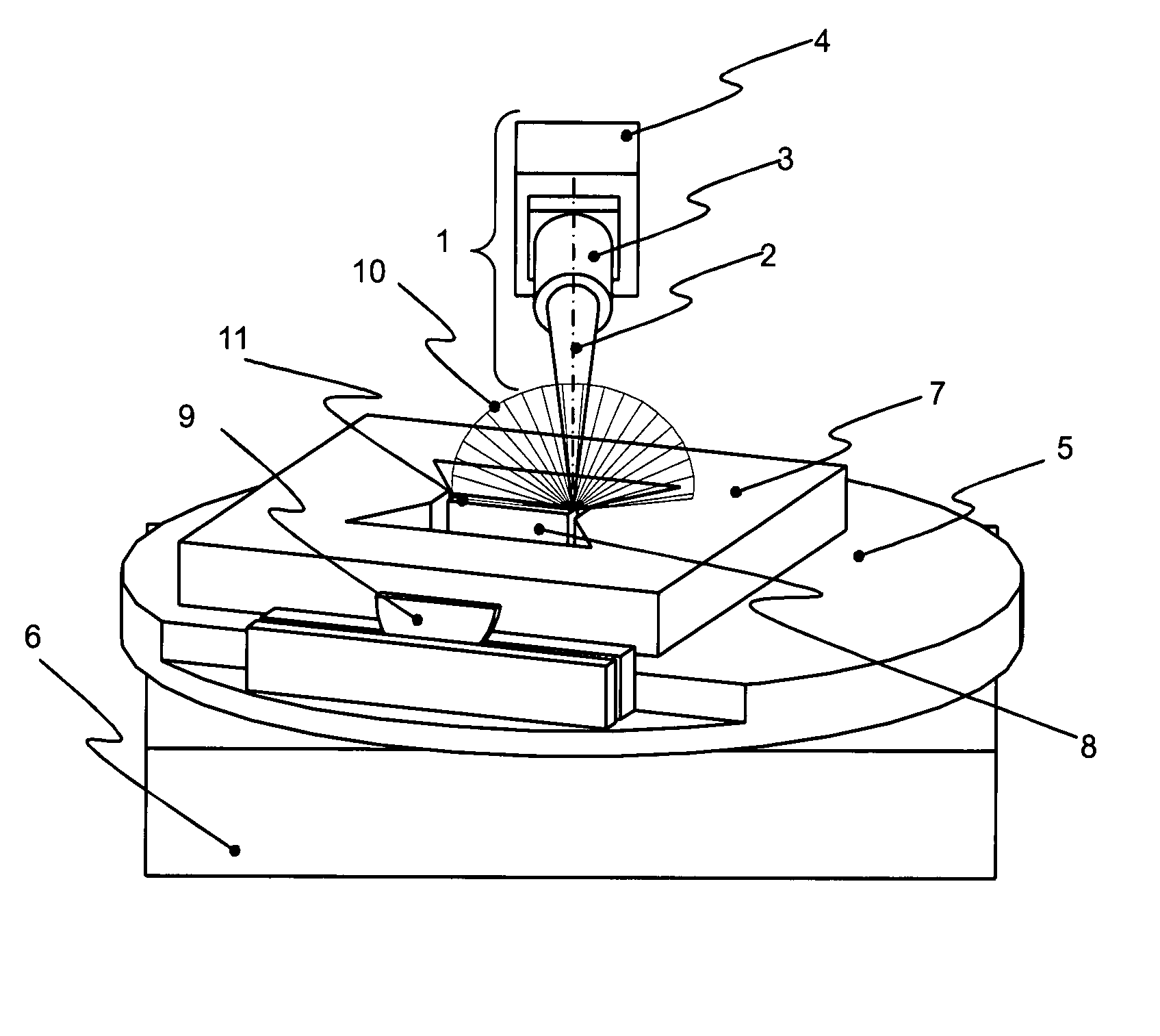
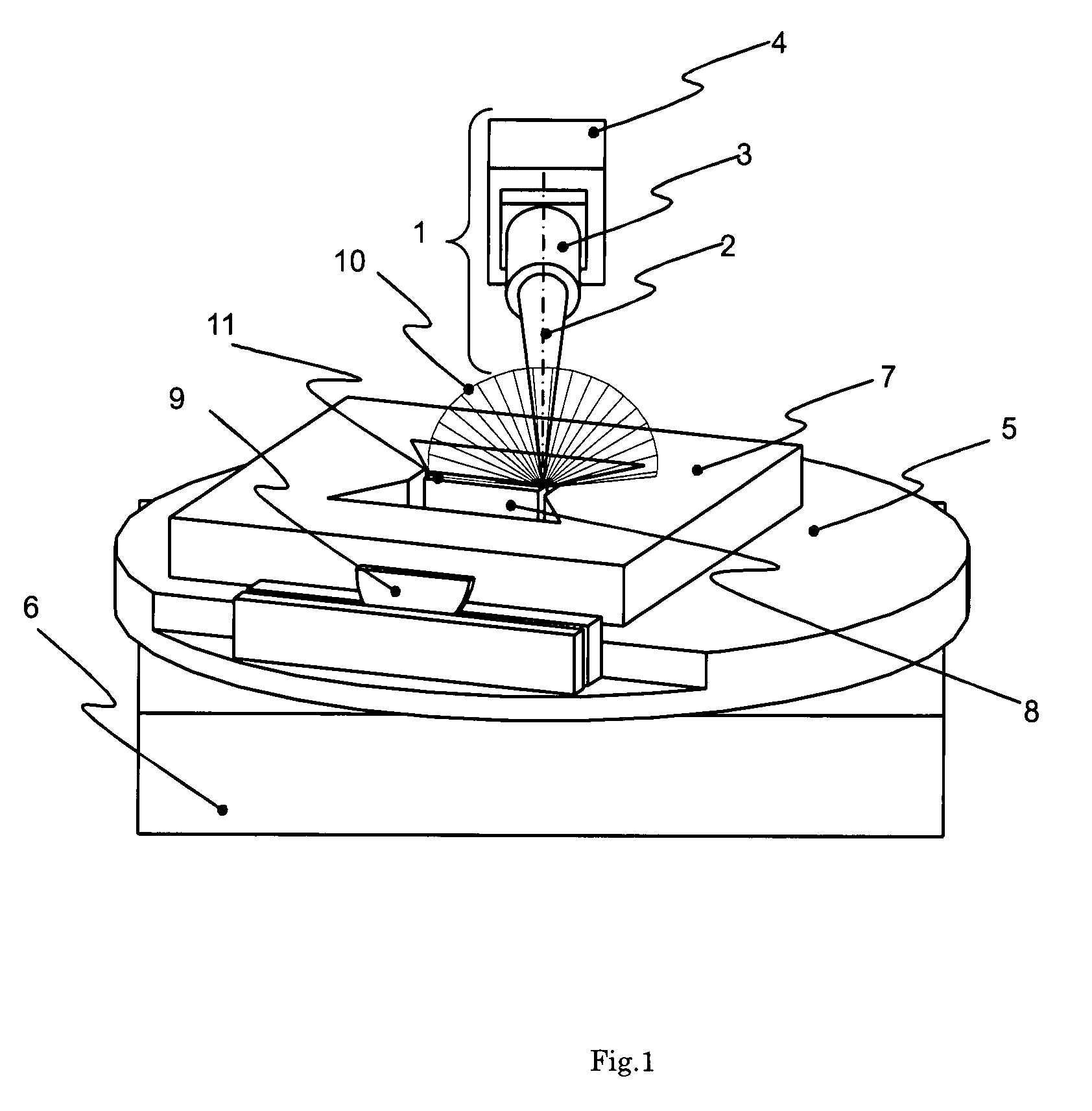
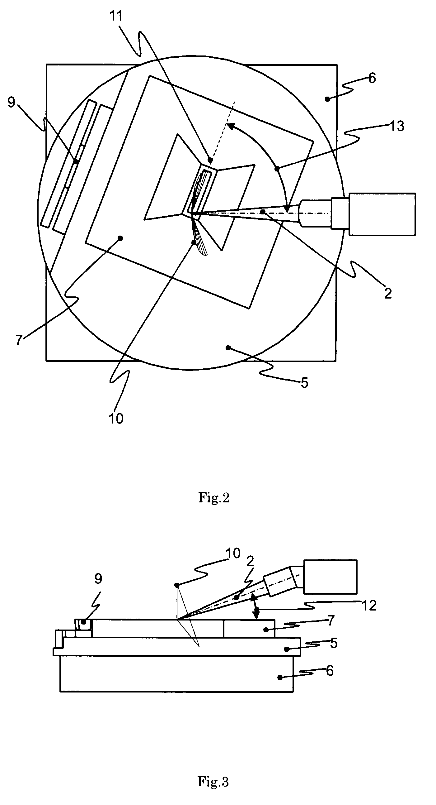
[0033]FIGS. 1 to 3 show schematic views of a sample preparing device in which the invention is embodied. FIG. 1 is a perspective view, FIG. 2 is a top view and FIG. 3 is a side view.

[0034]Size ratios are different from actual size ratios to show relations of parts in a way easy to understand.

[0035]Herein, as an example, there is disclosed a focused ion beam system in which the invention is incorporated.

[0036]A sample stage has five axes. A rotation stage 5 having a stage rotation axis is disposed on a XYZ orthogonal stage 6 to make the stage rotation axis cooperate with a XY axis, thereby allowing a rotation operation to be performed around an arbitrary point on the sample stage. Such a rotation operation is referred to as the compucentric rotation in the description described below. Further, these stages are disposed on a tilt stage. If necessary, an angle of a surface of the sample stage can be changed with respect to a focused ion beam. In the following description, it is assumed...

second embodiment

[0047]A second embodiment will be described which differs in form and function from the first embodiment. In this embodiment, the positional relation of the intersection line 11 and the sample piece 8 are different in the course of setting the positions of the sample piece 8 and the manipulator rotation axis 2 in the first embodiment. In this embodiment, the position of the sample piece 8 is set such that a short side of the upper plane of the upright plate-shaped sample piece 8 coincides with the intersection line azimuth 13. This position is a position obtained by rotating the result of the position setting performed in the first embodiment by 90 degrees. In this state, the sample piece 8 is fixed to the manipulator 1, the sample stage is retreated, and then the manipulator rotation axis 2 is operated in the same manner as in the first embodiment. In this state, a condition is necessarily provided in which a direction of the short side of the upper plane of the plate-shaped sample...

third embodiment

[0050]In the first and second embodiments, the upright plate-shaped sample piece 8 is disclosed as an example to observe the cross section thereof. However, in this embodiment, preparing a sample for performing TEM observation on the plane of the sample 7 is disclosed as an example. The ion beam etching using the focused ion beam system is performed only from the upper side or the tilted upper side of the sample in principle. Accordingly, for example, a sample piece for plane observation is prepared in a wedge shape such that a surface of the sample is one surface as shown in FIG. 11. A position of this sample piece 8 is set such that the intersection line 11 coincides with a direction to be set as a vertical direction when the sample piece is attached to the sample piece table 9. Then, the sample piece 8 is fixed to the manipulator 1, the sample stage is retreated, and then the manipulator rotation axis 2 is operated in the same manner as in the first and second embodiments. In thi...


PUM

PropertyMeasurementUnit
angleaaaaaaaaaa
anglesaaaaaaaaaa
angleaaaaaaaaaa

Abstract

A sample preparing device has a sample stage that supports a sample and undergoes rotation about a first rotation axis to bring a preselected direction of the sample piece into coincidence with an intersection line between a first plane formed by a surface of the sample piece and a second plane. A manipulator holds sample piece of the sample and undergoes rotation about a second rotation axis independently of the sample stage to rotate the sample piece to a preselected position in the state in which the preselected direction of the sample piece coincides with the intersection line. The manipulator is disposed relative to the sample stage so that an angle between the second rotation axis and the surface of the sample is in the range of 0° to 45°. The second plane corresponds to a plane obtained by rotating around the second rotation axis a line segment which is vertical to the surface of the sample and of which one end corresponds to an intersection between the surface of the sample and the second rotation axis.

Description

BACKGROUND OF THE INVENTION[0001]1. Field of the Invention[0002]The present invention relates to a focused ion beam system and a composite charged particle beam device for preparing a sample for a transmission electron microscope.[0003]2. Background Information[0004]Focused ion beam systems are widely used to prepare a sample for a transmission electron microscope (TEM). Particularly, in fields of process monitoring and failure analysis for semiconductor devices, the preparation of a sample by a focused ion beam is an essential technique because positioning accuracy of a sample piece is very high.[0005]The preparation of a TEM sample by a focused ion beam is performed such that a thin observing piece is prepared by positioning a site to be observed in a sample by an ion microscope image of a focused ion beam system and removing both sides of an observing cross section by ion beam etching. The prepared thin piece is moved to a sample table for TEM observation to be subjected to the T...

Claims


Application Information

Patent Timeline
Patent Type & Authority Patents(United States)
IPC IPC(8): H01J37/20G21K5/10G01N1/28
CPCH01J37/023H01J37/20H01J37/3056H01J2237/202H01J2237/204H01J2237/2062H01J2237/208H01J2237/31745H01J2237/31749
Inventor TAKAHASHI, HARUONAKATANI, IKUKOTASHIRO, JUNICHI
Owner HITACHI HIGH TECH SCI CORP
Why Eureka
Try Eureka