Method and apparatus for utilizing magnetic field modulation to increase the operating frequency of sensors

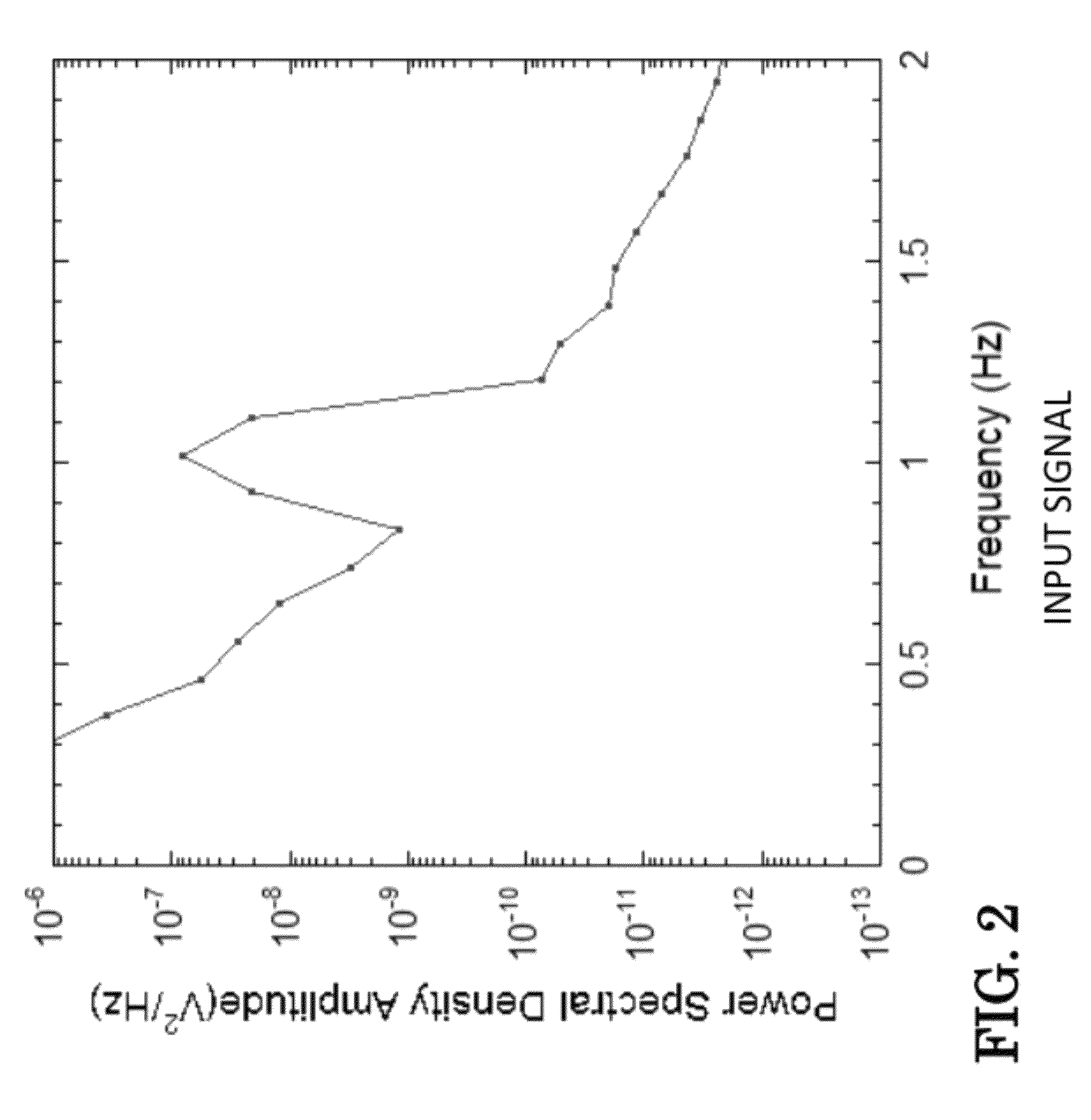
a technology of magnetic field and sensor, applied in the field of sensors, can solve the problems of considerable acoustic noise generated by the rotating disk movement, and achieve the effects of increasing the operating frequency of magnetoelectric (me) sensors, reducing the effect of 1/f noise, and increasing the operating frequency

Inactive Publication Date: 2012-07-17
US SEC THE ARMY THE
View PDF11 Cites 24 Cited by
  • Summary
  • Abstract
  • Description
  • Claims
  • Application Information

AI Technical Summary

Benefits of technology

[0008]The present invention is directed to a field modulation technique that increases the operating frequency of magnetoelectric (ME) sensors so that it has the capability of matching the mechanical resonance frequency of the sensor or alternatively solely increases the operating frequency. The resulting improvement reduces the effect of 1 / f noise that is inherent at low frequencies and may also improve the sensitivity by operating at the resonant frequency, where the sensor has a larger response. This technique, which is shown to apply to both symmetric and asymmetric ME sensors, relies on the strong, nonlinear magnetic field dependence of the magnetostriction. The combination of a lower 1 / f noise and the capability of enhanced response at resonance has increased the signal to noise ratio of a symmetric sensor by two orders of magnitude and lowered its detection limit to 7 pT / √{square root over (Hz)} at 1 Hz in a magnetically unshielded environment.
[0010]As shown in FIG. 1, the preferred embodiment assembly 10 comprises at least one coil 6 positioned as shown. When two coils are used, both coils have their field direction along the sense direction of the sensor. At least one or more coils 6 can be used to apply a DC field to bias the sensor; which affords the opportunity to remove the bias layer 2 from the assembly 10. An AC magnetic field that is large enough in magnitude is used to drive one or several of the magnetic components of the sensor into and out of a region of increased magnetic response at a frequency fm. Alternately to coils, a magnet(s) parallel to the sensor can be repeatedly cycled at fm to different positional offsets from the sensor. The stray fields will have a DC bias component and an AC field component at fm. In all instances, the modulating frequency operates to modulate the amplitude of the signal output of the sensor (the sensed signal). When the components, e.g., the flux concentrator (4,5), the biasing layer 2, and / or the magnetostrictive material (Metglas®) layer 1, are in the region of increased magnetic response, the sensor will be much less sensitive. Thus, either the field sensed due to changing the flux concentrator will be modulated at fm or the output amplitude of the sensor will be modulated at fm if the biasing magnet or magnetostrictive material is driven into and out of their region of increased magnetic response. In any case, the operating frequency of the sensor will be increased to higher frequencies; reducing 1 / f noise inversely proportional to frequency. A further possible advantage is that one can increase the frequency to particular frequencies where some sensors are more sensitive. Magnetoelectric sensors have increased sensitivity at their mechanical resonant frequency modes fr. For example, when detecting a low frequency signal fs, the coil is driven at fm sidebands appear at fm±fs. The modulation frequency fm can be picked for driving the magnetic material into and out of saturation so that one of the sidebands is at the resonant frequency, i.e.,fr=fm−fs or fr=fm+fs  (1)
[0012]Another preferred embodiment modulating magnetic field sensor device may comprise a base; a magnetic sensor operatively associated with the base structure for sensing a magnetic field; at least one coil for creating a magnetic field around the magnetic sensor; at least one coil adapted to be connected to an alternating current source; whereby alternating current passing through the coil operates to modulate the magnetic field at the magnetic sensors and shift the frequency of the magnetic field that is sensed by the magnetic sensors to a higher frequency to thereby minimize 1 / f-type noise, where f is the frequency of operation of the magnetic sensor. Optionally, the device may comprise a flux concentrator on one side or both sides of said magnetic sensor.

Problems solved by technology

U.S. Pat. No. 7,898,247 discloses a method based on using a rotating disc containing flux concentrators and guides which can be used with a larger sensor, but the motion of the rotating disk generates considerable acoustic noise.

Method used


Image

  • Method and apparatus for utilizing magnetic field modulation to increase the operating frequency of sensors
  • Method and apparatus for utilizing magnetic field modulation to increase the operating frequency of sensors
  • Method and apparatus for utilizing magnetic field modulation to increase the operating frequency of sensors

Examples


Embodiment Construction

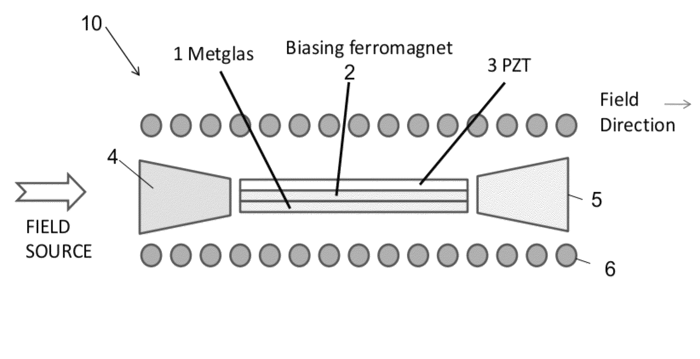
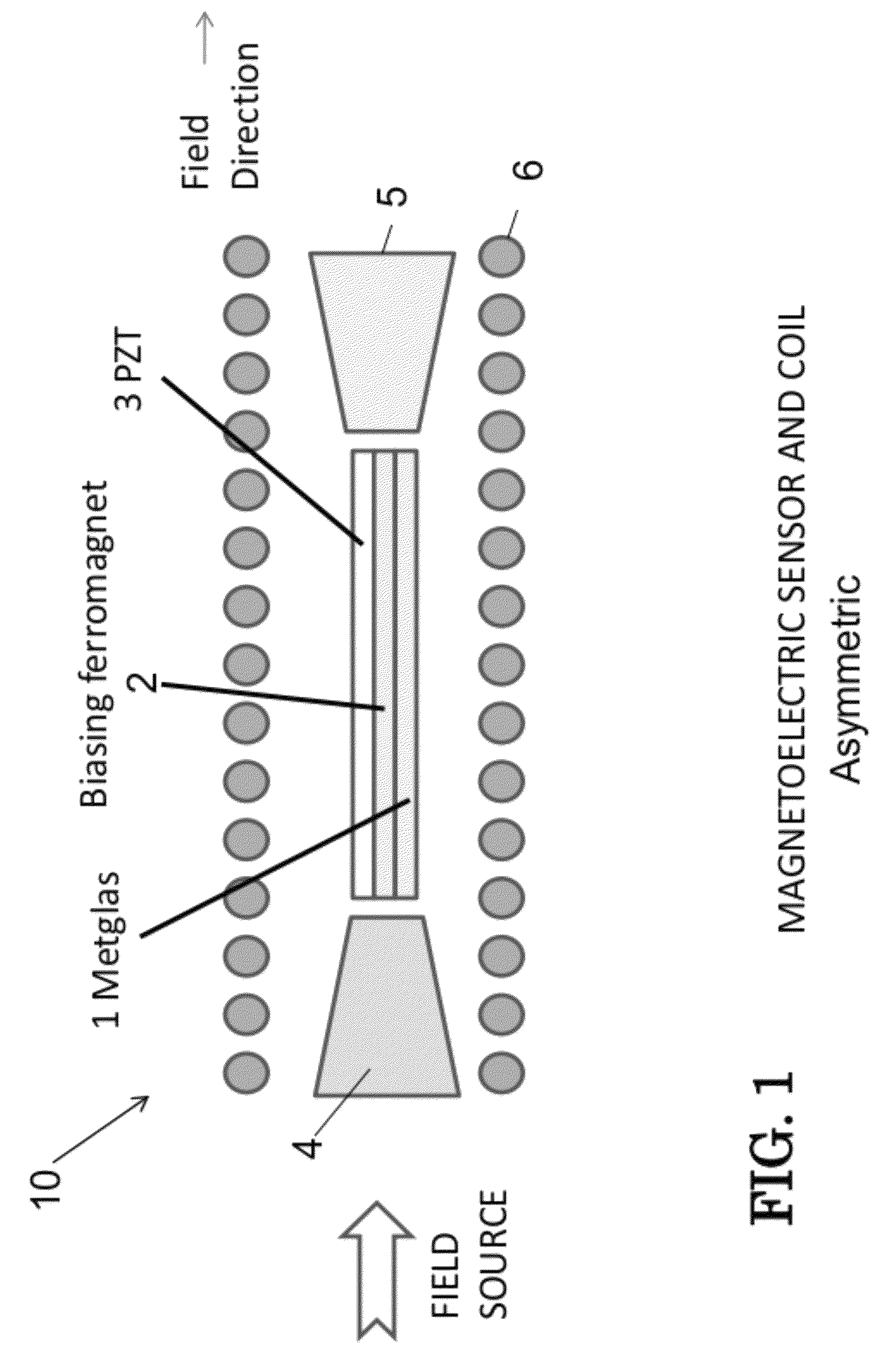
[0029]The present invention now will be described more fully hereinafter with reference to the accompanying drawings, in which embodiments of the invention are shown. However, this invention should not be construed as limited to the embodiments set forth herein. Rather, these embodiments are provided so that this disclosure will be thorough and complete, and will fully convey the scope of the invention to those skilled in the art. In the drawings, the thickness of layers and regions may be exaggerated for clarity. Like numbers refer to like elements throughout. As used herein the term “and / or” includes any and all combinations of one or more of the associated listed items.

[0030]The terminology used herein is for the purpose of describing particular embodiments only and is not intended to limit the full scope of the invention. As used herein, the singular forms “a”, “an” and “the” are intended to include the plural forms as well, unless the context clearly indicates otherwise. It wil...


PUM


Abstract

A system for modulating a magnetic field sensor device comprising: a base; a magnetic sensor comprising a plurality of magnetic components; at least one coil for creating a magnetic field around the magnetic sensor; the at least one coil adapted to be connected to an alternating current source that passes through the coil to modulate the magnetic field at the magnetic sensor and drive at least one of the magnetic components of the magnetic sensor into and out of its region of increased magnetic response while shifting the frequency of the magnetic field that is sensed by the magnetic sensors a higher frequency to thereby minimize 1 / f-type noise, where f is the frequency of operation of the magnetic sensor. The method comprises forming at least one coil around the magnetic sensor; connecting the coil to an alternating current power source; and modulating the current from the power source.

Description

CROSS REFERENCE TO RELATED APPLICATIONS[0001]The application claims priority to Provisional Application No. 61 / 475,958 filed Apr. 15, 2011, entitled ‘Method and Apparatus for Utilizing Magnetic Field Modulation to Increase the Operating Frequency of Sensors,” hereby incorporated by reference.GOVERNMENT INTEREST[0002]The invention described herein may be manufactured, used, and / or licensed by or for the United States Government.FIELD OF THE INVENTION[0003]This invention relates generally to sensors, more particularly to magnetic field modulations of magnetic sensors.BACKGROUND OF THE INVENTION[0004]Pursuant to 35 U.S.C. §103(c)(2), the claimed invention was made by an employee of a party to a joint research agreement and as a result of activities undertaken within the scope of the joint research agreement. The parties to the joint research agreement were Virginia Polytechnic Institute & State University and the United States Air Force (U.S. Government).[0005]Methods of modulating the...

Claims


Application Information

Patent Timeline
Patent Type & Authority Patents(United States)
IPC IPC(8): G01R33/02G01R33/06
CPCG01R33/0041
Inventor EDELSTEIN, ALAN SHANE
Owner US SEC THE ARMY THE
Why Eureka
Try Eureka