Method and apparatus for low cost, long range, power efficient, wireless system with enhanced functionality

a wireless system and wireless technology, applied in transmission systems, instruments, climate sustainability, etc., can solve problems such as system latency that can be reached at an unacceptable level, and achieve the effects of reducing system latency, reducing power consumption, and reducing power consumption

Active Publication Date: 2012-08-21
III HLDG 1
View PDF7 Cites 15 Cited by
  • Summary
  • Abstract
  • Description
  • Claims
  • Application Information

AI Technical Summary

Benefits of technology

[0009]The present invention provides a method and system for establishing a highly mobile, long range secure wireless network with dynamic topologies and near full connectivity with acceptable latency using low cost, low power, compact and lightweight devices. One aspect of the system provides a highly mobile network with dynamic network topologies and a time varying wireless medium that has neither absolute nor readily observable boundaries outside of which radio nodes are known to be unable to receive network frames. The desirable open field boundary of the system is about 1 mile in radius from the base station node. While boosting the transmit power can increase the transmission distance, it is also desirable to meet FCC requirements and maintain a low power, light weight, compact form factor which is portable or can be embedded into other devices, avoids an excessive heat dissipation requirement on the mobile node, and avoids the use of large battery. While a lower data rate can assist in providing increased range, it also increases the duration a medium is occupied. As a result, when the number of mobile nodes in the network increases, the system latency can increase to an unacceptable level. While most of the conventional networks emphasize increased capacity and data throughput, the present invention provides a range increase with acceptable battery size and system latency.
[0010]The present invention uses a low complexity, constant envelope modulation with a low data rate which is insensitive to the nonlinearity allowed for high efficiency amplifiers both in the transmitter and the receiver. The system employs a synchronized time slot frequency hopping technique, in which the base station node periodically transmits beacons and the mobile nodes are time synchronized to the base station node and hop with the same pseudo-random pattern. In order to reduce the system latency and power consumption, short packets, optimized to carry essential information but expandable to support other system functions, are employed for transmitting and receiving the system data. To deal with multipath and fading, the present invention employs both antenna diversity and the frequency (time) diversity. The frequency diversity is a result of the frequency hopping technique. This combination ensures that the longest range can be achieved with lowest power consumption.
[0011]In order to simplify the system processing complexity, the present invention employs a slotted time frame structure with two types of time slots. A “contention-access time” slot allows uncoordinated access to the network by the mobile nodes and an “allocated time” slot provides dedicated time slots to certain nodes which can communicate in a coordinated and an interference free fashion within the network. Such a frame structure maintains the simplicity of low power operation and low complexity random access by mobile nodes while, at the same time, supporting a number of advanced features such as capacity expansion, reduced latency, and range extension.

Problems solved by technology

As a result, when the number of mobile nodes in the network increases, the system latency can increase to an unacceptable level.

Method used


Image

  • Method and apparatus for low cost, long range, power efficient, wireless system with enhanced functionality
  • Method and apparatus for low cost, long range, power efficient, wireless system with enhanced functionality
  • Method and apparatus for low cost, long range, power efficient, wireless system with enhanced functionality

Examples


Embodiment Construction

[0025]The present invention provides a low power, long range, secure, and fully mobile (base station and handset) radio network. The present invention achieves a long range while maintaining low power consumption. Other aspects of the invention deal with low network latency while accommodating a large number of mobile nodes and achieving full connectivity of the system. The present invention provides a method and system for establishing a highly mobile, long range, secure, wireless network with dynamic topologies, near full connectivity and acceptable latency using low cost, low power, compact and lightweight devices.

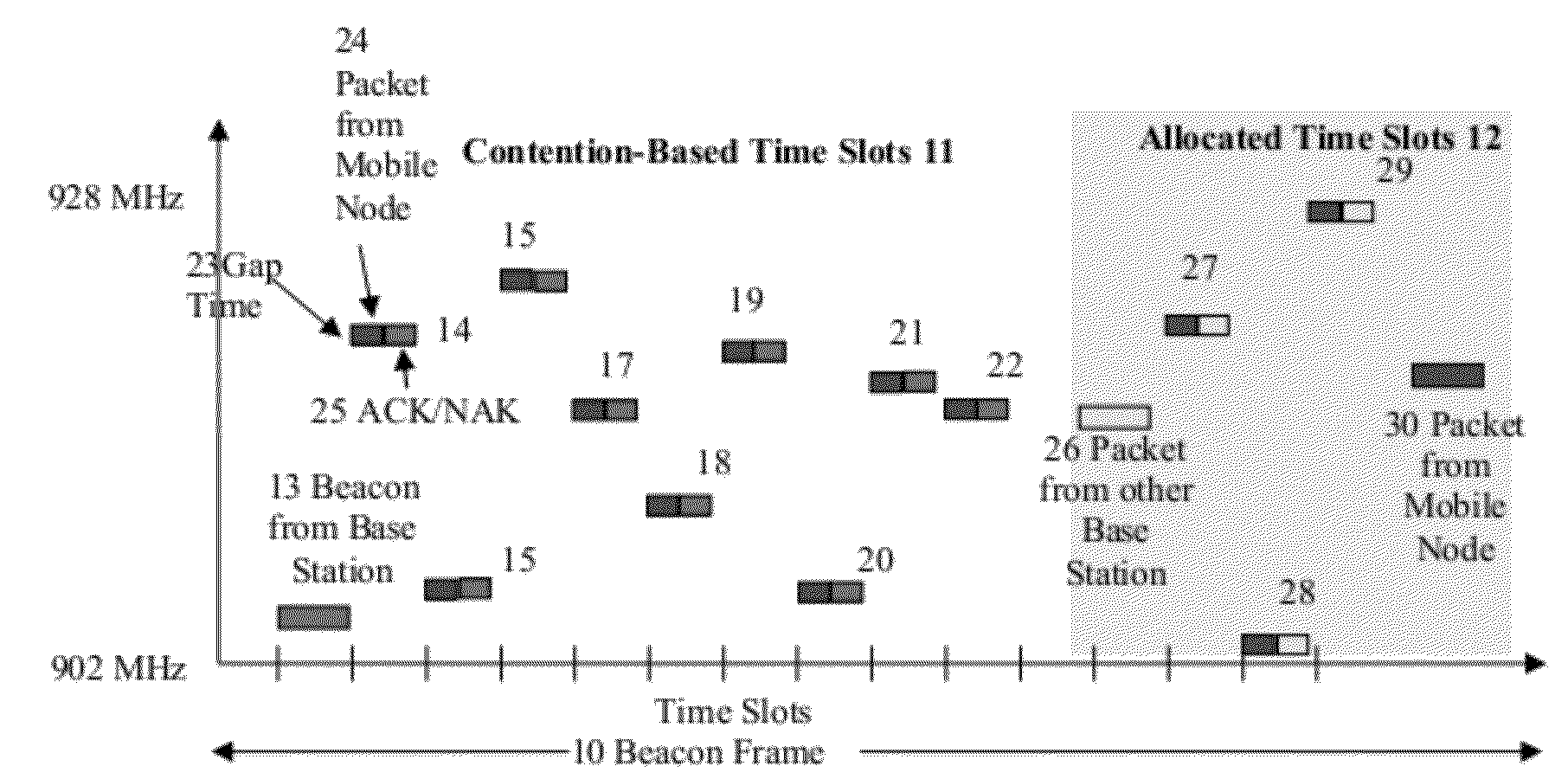
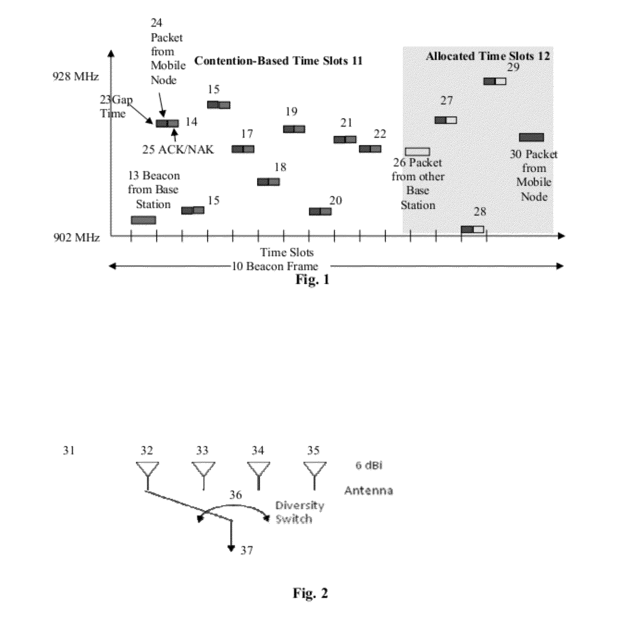
[0026]A UHF slow frequency hopping system with Minimum Shift Keying (MSK), Gaussian Minimum Shift Keying (GMSK), Frequency Shift Keying (FSK) or Staggered Quadrature Phase Shift Keying (SQPSK) types of constant envelope modulation schemes that can be demodulated with a simple receiver is used in the present invention. It is suitable for an implementation with a low cost...


PUM


Abstract

The present invention provides a method and system for establishing a highly mobile, long range secure wireless network with dynamic topologies and near full connectivity with acceptable latency using low cost, low power, compact and lightweight devices. One aspect of the system deals with a highly mobile network with dynamic network topologies and a time varying wireless medium that has neither absolute nor readily observable boundaries outside of which radio nodes are known to be unable to receive network frames, although the desirable open field boundary is 1 mile in radius from a base station node. A synchronous frequency hopping technique is used with mobile nodes that can become slave base station nodes to a master base station node to increase the effective range of the master base station without increasing the transmit power. Furthermore, the use of adjustable sleep times for the mobile nodes, as well as a novel clock calibration method, provides a substantial range increase with acceptable battery size and system latency.

Description

BACKGROUND OF THE INVENTION[0001]1. Field of the Invention[0002]The present invention provides a system and apparatus for a low cost, long range, power efficient wireless system that provides identification and locational information.[0003]2. Description of Related Art[0004]The wireless Local Area Networks (LAN), based on the 802.11(a / b / g / n) standard, support short range communications between portable devices such as notebooks. The system design employs Time Division Duplex (TDD) and Orthogonal Frequency Division Multiplexing (OFDM) modulation that is optimized for high data throughput in an indoor fading environment. In order to fairly share the wireless medium among different devices, the network protocol tries to keep a single node from occupying the medium for a long period of time by limiting the lowest allowable signaling rate. Since the required signal-to-noise ratio for a given bandwidth is proportional to the signaling rate, the achievable communication range for a wireles...

Claims


Application Information

Patent Timeline
Patent Type & Authority Patents(United States)
IPC IPC(8): G08C17/00
CPCH04B1/713Y02B60/50
Inventor WARNER, ROBERTWANG, JAMESWINTERS, JACK
Owner III HLDG 1
Why Eureka
Try Eureka