Exhaust sound attenuation device and method of use

a technology of exhaust sound and attenuation device, which is applied in the direction of sound absorption, gas passage, gas chamber, etc., can solve the problems of limited noise reduction capability, adversely affecting the operation efficiency of the device, and mufflers that create substantial back pressure or do not adequately reduce the sounds, etc., to achieve sufficient low density of material and reduce low frequency sound

Inactive Publication Date: 2012-09-04
HUFF DENNIS L +1
View PDF47 Cites 23 Cited by
  • Summary
  • Abstract
  • Description
  • Claims
  • Application Information

AI Technical Summary

Benefits of technology

[0008]A layer of sound absorbing material surrounds the tubular pipe structure and serves to attenuate the higher frequency sound waves. The density of the material is sufficiently low to allow low frequency sound waves to pass through the material. If the sound absorber is not self supporting, an enclosure such as a mesh screen retains the sound absorber in place. The enclosure is largely transparent to the low frequency sound waves. Finally, a frusto-conical resonant chamber surrounds the sound absorber, said resonant chamber being either converging or diverging from the inlet to the outlet. The resonant chamber serves to reduce low frequency sound.

Problems solved by technology

The pressure and flow pulses are sources of noise, and any restrictions in the flow can create a back pressure that adversely affects the operational efficiency of the device.
In many cases, the designs of these mufflers create substantial back pressure or do not adequately reduce the sounds that are emitted from an exit such as a tail pipe.
There are also “straight through” muffler designs that reduce the flow losses, but they have limited noise reduction capability.
However, they often introduce a low frequency system resonance due to acoustic interaction with the tailpipe.

Method used


Image

  • Exhaust sound attenuation device and method of use
  • Exhaust sound attenuation device and method of use
  • Exhaust sound attenuation device and method of use

Examples


example 1

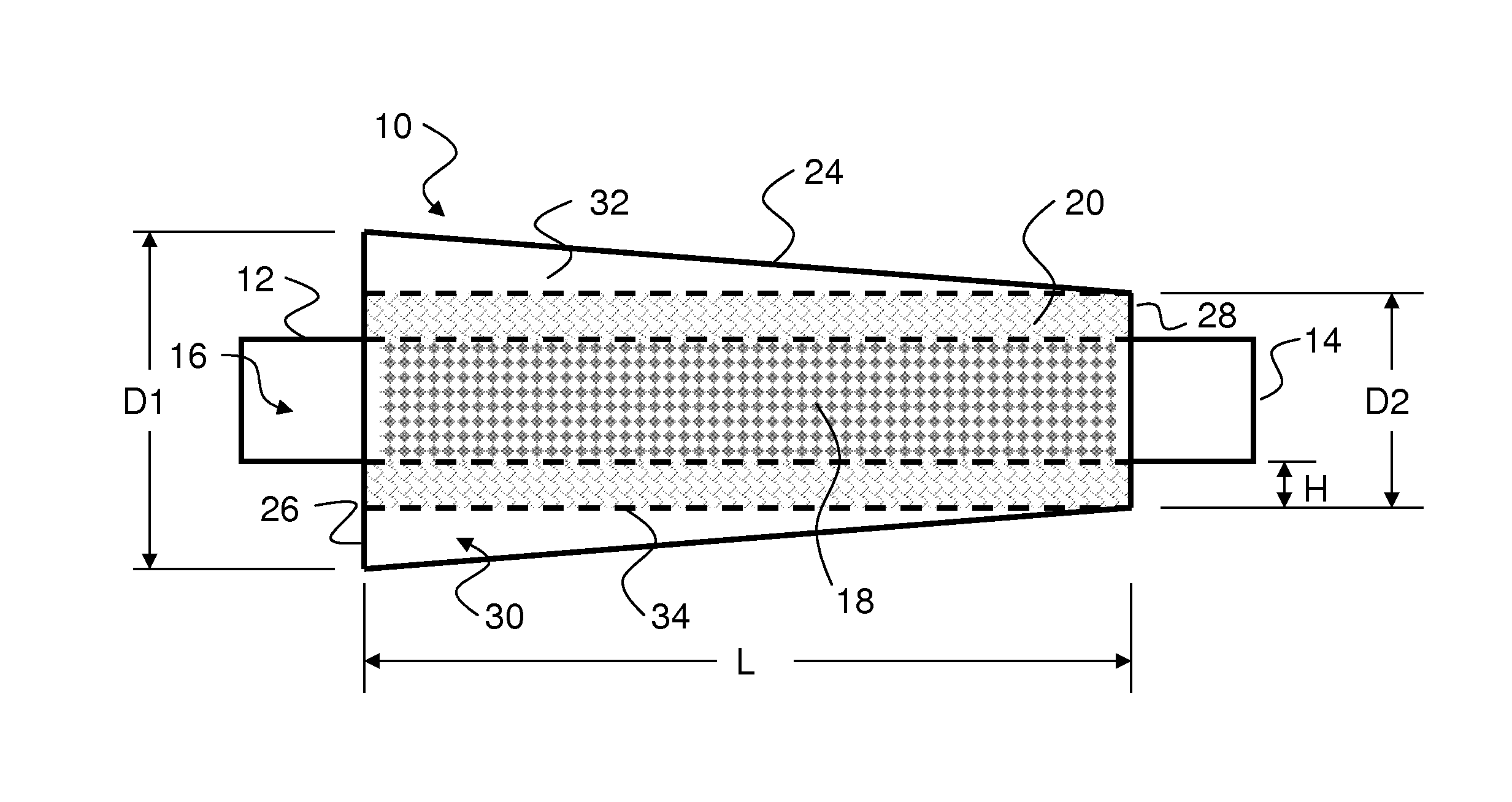
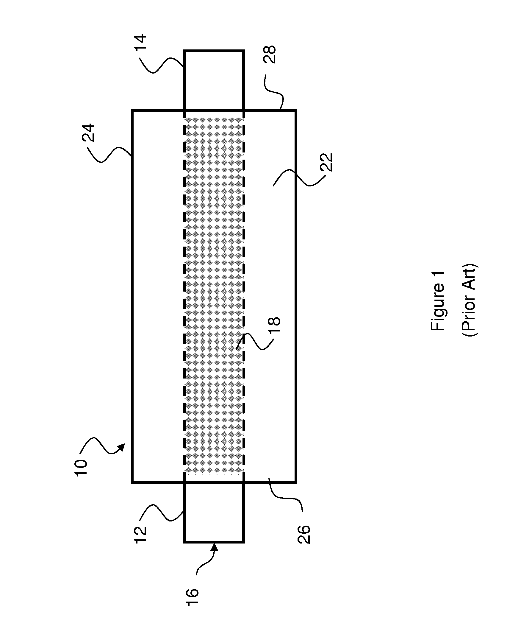
[0026]A 175.25″ long straight pipe was used to define the target resonant frequencies with values that are realistic for an automobile application. A speaker source was used to insert white noise at the inlet end of the pipe. Sound measurements were made at the pipe exit to compare the acoustic spectra with and without a muffler, defined as “insertion loss”. The exhaust pipe is 2.5″ in diameter. The front (inlet) of the mufflers is located 113.25″ from the speaker flange. The muffler designated “Muffler 10A” contains Owen-Corning Advantex 162A fiber bulk absorber material with a bulk density of 0.15 g / cm3 for sound dissipation. The dissipation material fills the volume between the outer perforated pipe 34 and the perforated through pipe 16. The muffler designated “Muffler 10B” does not have the dissipative layer, but does contain the perforated pipes 34, 16.

[0027]Narrowband sound pressure level (SPL) spectra were measured for two frequency ranges, 0 to 1250 Hz (FIG. 5) and 0 to 10 k...

example 2

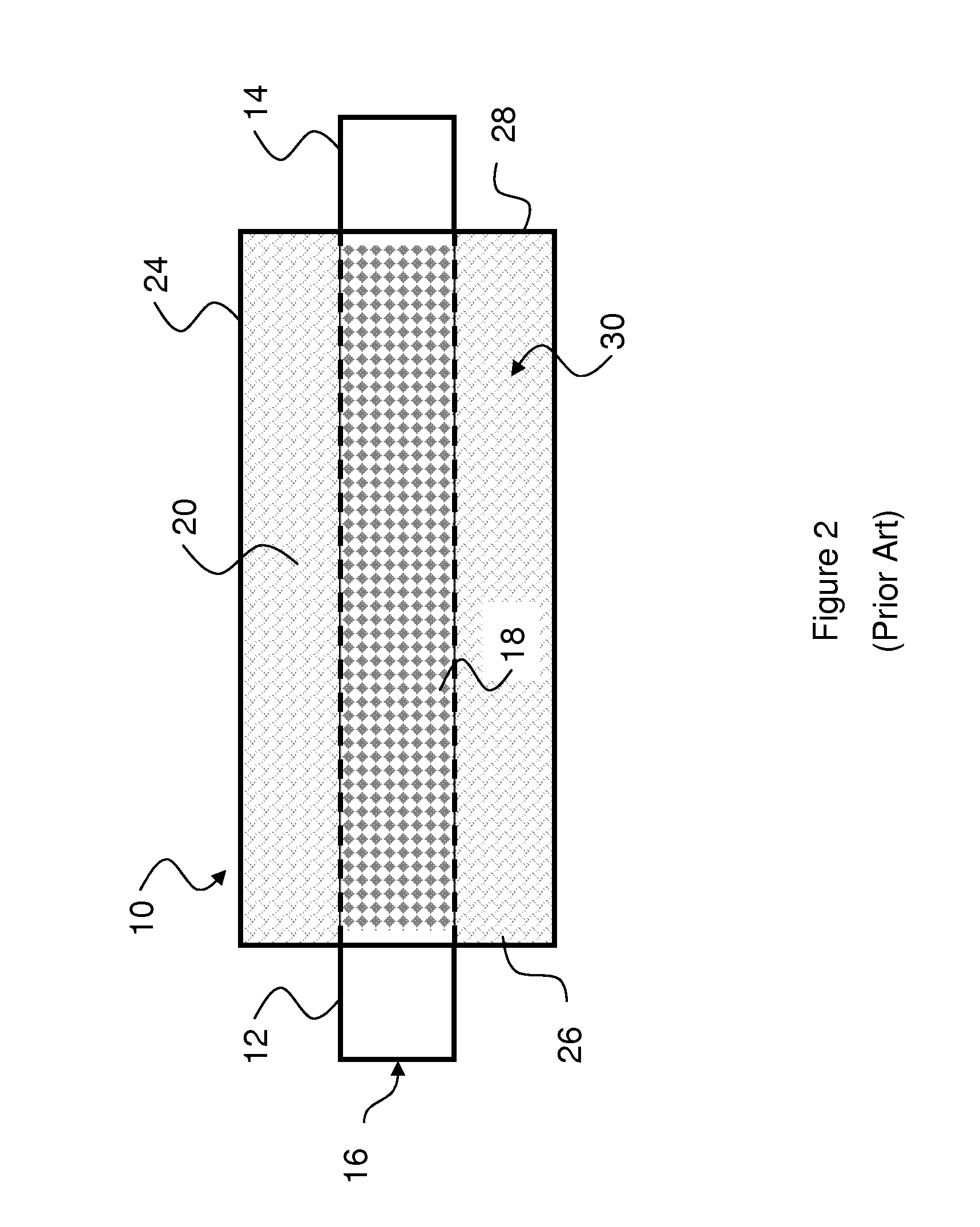
[0028]Another advantage to the frusto-conical resonant chamber is the ability to control the low frequency system resonance that occurs with a resonator near the tailpipe. A 179.75″ straight pipe was used as a comparison for this test. The mufflers were mounted near the end of the straight pipe, with the rear of the muffler located 15″ from the tailpipe exit. FIG. 7 shows the sound spectra from 0 to 300 Hz measured at the end of a straight pipe (solid black) compared to the spectra from three different mufflers: an expansion chamber partially filled with dissipation (Muffler 9A, bold dotted line); a converging muffler (Muffler 10A, light solid line); and a diverging muffler by switching the direction of Muffler 10A (light dotted line). Notice the tone that is measured near 40 Hz for Muffler 9A that was not present for the straight pipe data. This is the low frequency system resonance that occurs due to the interaction of the resonator (expansion chamber) with the tailpipe. When eith...


PUM

PropertyMeasurementUnit
frequencyaaaaaaaaaa
densityaaaaaaaaaa
densityaaaaaaaaaa

Abstract

A sound muffler combines a resonator chamber with a dissipative layer surrounding a through pipe. The muffler provides sound attenuation over a wide range of sound frequencies while maintaining unimpeded flow of gases through the pipe. This attenuation is achieved by combining dissipation with a frusto-conical resonant chamber. The dissipation is achieved by encircling the through passage with a layer of low density material such as metallic or ceramic foam or loosely packed fibers of a heat resistant material. The low density material attenuates the high frequency waves while permitting the passage of low frequency sound waves into the frusto-conical resonant chamber.

Description

RELATED APPLICATION[0001]This application claims the benefits of the following provisional patent application previously filed in the United States Patent and Trademark Office by common inventors Dennis L. Huff and Ronald G. Huff entitled “EXHAUST SOUND ATTENUATION DEVICE AND METHOD OF USE,” filed Oct. 4, 2010, Ser. No. 61 / 389,366, Confirmation No. 1136.BACKGROUND OF THE INVENTION[0002]Devices such as fans, internal combustion engines and compressors generate pressure pulses and flow pulses in their exhausts. In particular, with devices such as the internal combustion engines, products of combustion comprise the flow pulses. The pressure and flow pulses are sources of noise, and any restrictions in the flow can create a back pressure that adversely affects the operational efficiency of the device. The equipment that is used to mitigate or reduce the noise level of the pressure and flow pulses in the exhaust gas is commonly referred to as a muffler.[0003]There are many different desi...

Claims


Application Information

Patent Timeline
Patent Type & Authority Patents(United States)
IPC IPC(8): F01N1/10F01N1/24F01N1/00
CPCF01N1/026F01N1/04F01N2310/14F01N2470/02F01N2490/18
Inventor HUFF, DENNIS L.HUFF, RONALD G.
Owner HUFF DENNIS L
Why Eureka
Try Eureka