Inlet system for an engine

a technology of inlet system and engine, which is applied in the direction of liquid fuel engines, machines/engines, combustion air/fuel air treatment, etc., can solve the problems of reducing compressor stage efficiency, and rotating stall of compressors, so as to reduce the distance from the inlet port, reduce the cross-sectional area of the inlet duct, and increase the effective flow area through the flow management device

Active Publication Date: 2012-10-16
FORD GLOBAL TECH LLC
View PDF53 Cites 7 Cited by
  • Summary
  • Abstract
  • Description
  • Claims
  • Application Information

AI Technical Summary

Benefits of technology

[0009]According to an embodiment of the disclosure there is provided an inlet system for an engine comprising an inlet manifold for supplying air to the engine, a radial compressor having a compressor wheel mounted in a compressor housing for rotation about an axis, an inlet port in the housing through which gas is supplied to the compressor wheel, an outlet port in the housing through which gas at increased pressure is supplied to the inlet manifold, an inlet duct connected to the inlet port to provide air to the radial compressor, and a flow management device having a number of radially-extending fixed vanes positioned in the inlet duct upstream from the inlet port to impart a swirling motion to the gas entering through the inlet port. The inlet duct has a tapering portion extending towards the inlet port such that the cross-sectional area of the inlet duct decreases as the distance from the inlet port decreases. The flow management device is positioned at a distance upstream of the inlet port such that the effective flow area through the flow management device is greater than it would be if the flow management device were positioned adjacent the inlet port and is greater than a minimum value so as to prevent excessive back pressure at high gas flow rates.
[0013]The flow management device may be optimized to reduce the relative velocity between the gas entering through the inlet and the compressor wheel without significantly reducing pump efficiency.
[0014]The flow management device may be optimized to reduce the relative velocity between the gas entering through the inlet and the pump member without significantly reducing pump efficiency.
[0015]The flow management device may be optimized to reduce: the probability of rotating stall, the probability of surge and the generation of noise.
[0020]According to an embodiment of the disclosure, there is provided a method for improving the performance of a radial compressor, including: locating a flow management device having a number of fixed vanes upstream from the compressor to produce a pre-swirl to the air entering the compressor and optimizing the flow management device so as to ensure the back pressure produced by the flow management device is below a predetermined limit.

Problems solved by technology

It is a problem with such radial compressors that the flow field presented to the inlet of a turbocharger compressor influences the operation of the compressor.
A high relative velocity between the working fluid (air) and the vanes of the compressor can lead to separation of the flow from the suction side of the vanes resulting in compressor rotating stall and / or compressor surge.
These phenomena give rise to reduced compressor stage efficiency and undesirable noise radiation, sometimes referred to as turbocharger whoosh.
However, such flow management devices may create a further problem because they reduce the effective cross-sectional area of the inlet to the compressor and thereby restrict the flow of air to the compressor.
This may result in the compressor being starved for air causing runaway or inlet manifold instability such as back flow particularly at high speeds and loads.
Although the occurrence of excessive back pressure can be overcome by the use of vanes whose rotational position can be adjusted, such an arrangement is undesirable for many small vehicle applications because of the added cost and complexity.
In addition to the cost and complexity issues associated with the use of a flow management device having moveable vanes, there may also be a problem of package space when the radial compressor is one fitted to a small vehicle.

Method used


Image

  • Inlet system for an engine
  • Inlet system for an engine
  • Inlet system for an engine

Examples


Embodiment Construction

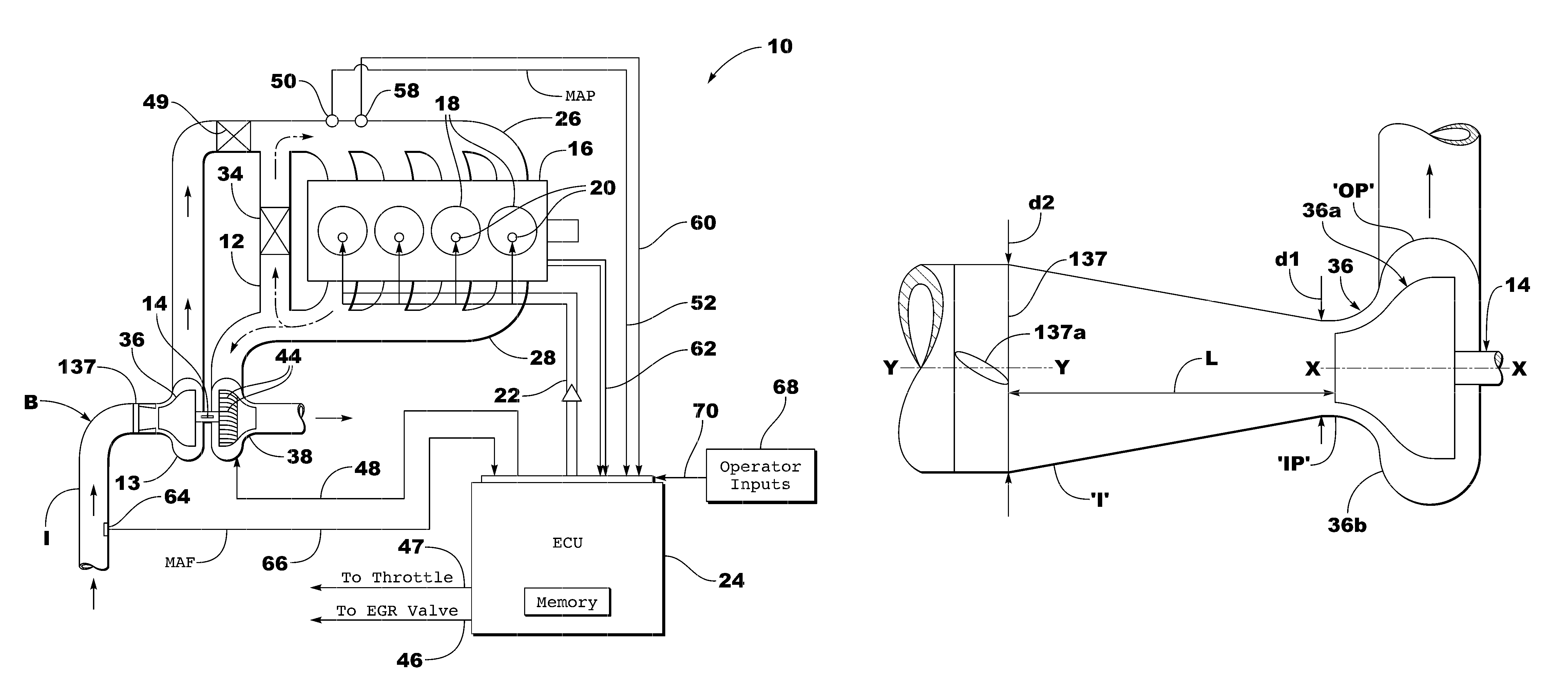
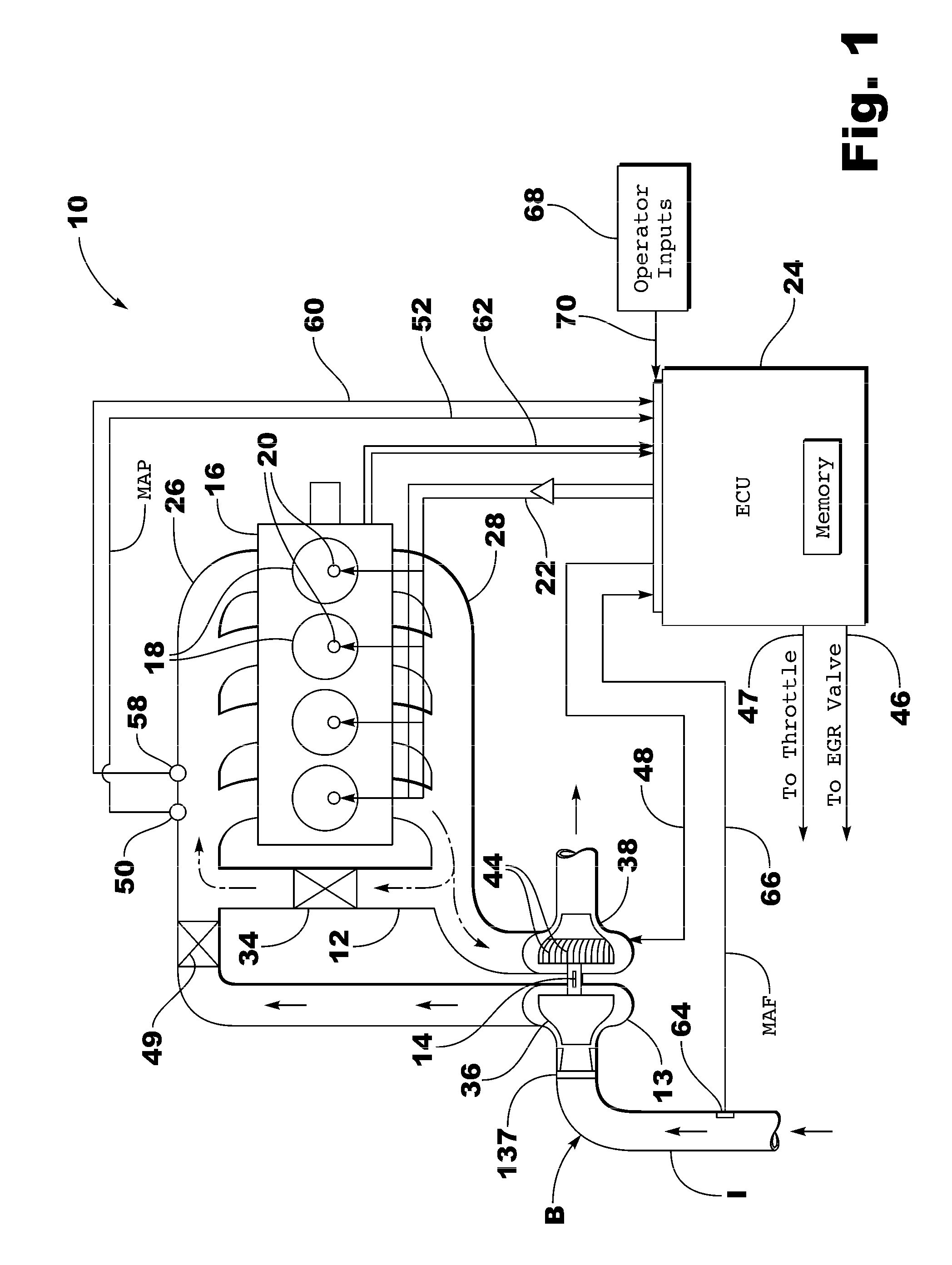
[0028]Referring now to FIGS. 1 and 3, a spark ignition engine system 10 is shown. The engine includes an exhaust gas recirculation (EGR) system 12 and a turbocharger 14 having a radial compressor portion 36 and a turbine portion 38 with the turbine portion 38 having an inlet flow control device 44 with open and closed positions. The inlet flow control device 44 is an inlet area control device for the turbine portion 38 in the form of the set of moveable turbine vanes.

[0029]A representative engine block 16 is shown having four combustion chambers 18 each of which includes a fuel injector 20. The duty cycle of the fuel injectors 20 is determined by an engine control unit (ECU) 24 and transmitted along signal line 22. Air enters the combustion chambers 18 through the inlet or intake manifold 26 and combustion gases are exhausted through the exhaust manifold 28.

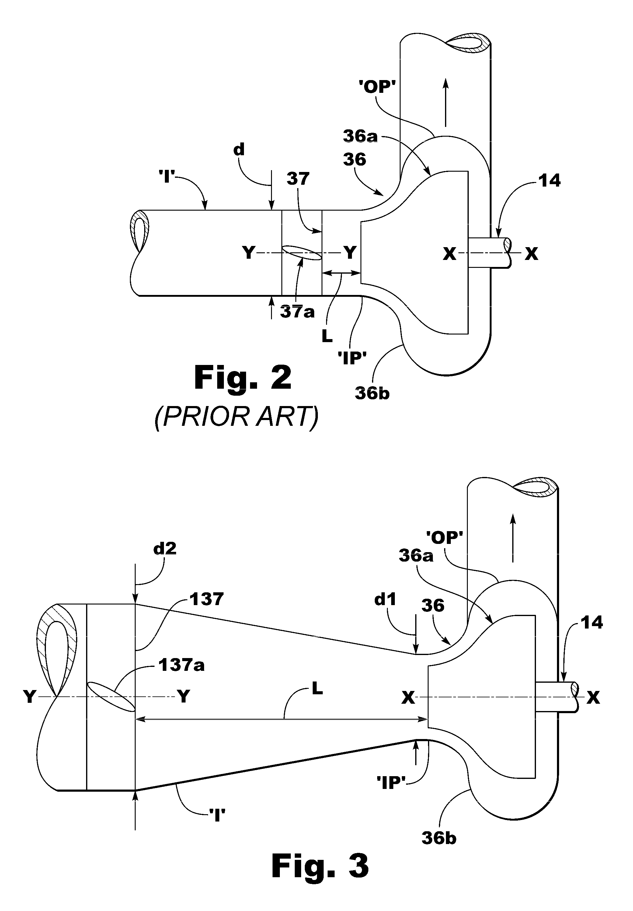
[0030]A flow management device 137 is positioned upstream from the radial compressor 36 in an inlet duct T which extends to an ...


PUM


Abstract

An apparatus for improving the performance of a radial compressor 36 forming part of an inlet system of an engine 10 is disclosed in which the configuration and positioning of a flow management device 137 used to generate pre-whirl is optimized so as to produce a pressure drop below a maximum acceptable level. An inlet duct ‘I’ connected to the radial compressor 36 has a tapered end portion so that a flow management device 137 of a larger diameter d2 can be accommodated than the diameter d1 of an inlet port ‘IP’ to the radial compressor 36.

Description

CROSS-REFERENCE TO RELATED APPLICATIONS[0001]This application claims foreign priority benefits under 35 U.S.C. §119(a)0(d) to GB 0821089.0 filed Nov. 19, 2008, which is hereby incorporated by reference in its entirety.BACKGROUND[0002]1. Technical Field[0003]This disclosure relates to improving the performance of a radial compressor and in particular to improving the performance of a radial compressor used for increasing the inlet pressure of an internal combustion engine equipped with a turbocharger or supercharger.[0004]2. Background Art[0005]It is well known to use a radial compressor in the form of a turbocharger or supercharger to increase the pressure of the air entering an engine to reduce emissions and / or increase power.[0006]It is a problem with such radial compressors that the flow field presented to the inlet of a turbocharger compressor influences the operation of the compressor. A high relative velocity between the working fluid (air) and the vanes of the compressor can ...

Claims


Application Information

Patent Timeline
Patent Type & Authority Patents(United States)
IPC IPC(8): F02B33/44F02B31/00F02M29/02F01D1/02F04D29/44F04D29/52
CPCF04D29/4213F04D29/441Y02T10/146F05D2250/51Y02T10/12F04D27/0246F04D27/0269F04D29/444
Inventor CAPON, GEOFFREY CHARLESLEONG, WA-UN ALEXISMARTIN, SCOTT JAMES
Owner FORD GLOBAL TECH LLC
Why Eureka
Try Eureka