Semiconductor device and method of manufacturing the same
a semiconductor chip and semiconductor technology, applied in the direction of semiconductor devices, semiconductor/solid-state device details, electrical equipment, etc., can solve the problems of reducing the joint strength, affecting the performance of the semiconductor chip, and the ag paste or between the metal leadframe and the ag paste in the semiconductor chip is decreased, so as to prevent the fatigue failure of the metal portion and increase the joint strength and bendability of the bonding portion
- Summary
- Abstract
- Description
- Claims
- Application Information
AI Technical Summary
Benefits of technology
Problems solved by technology
Method used
Image
Examples
first embodiment
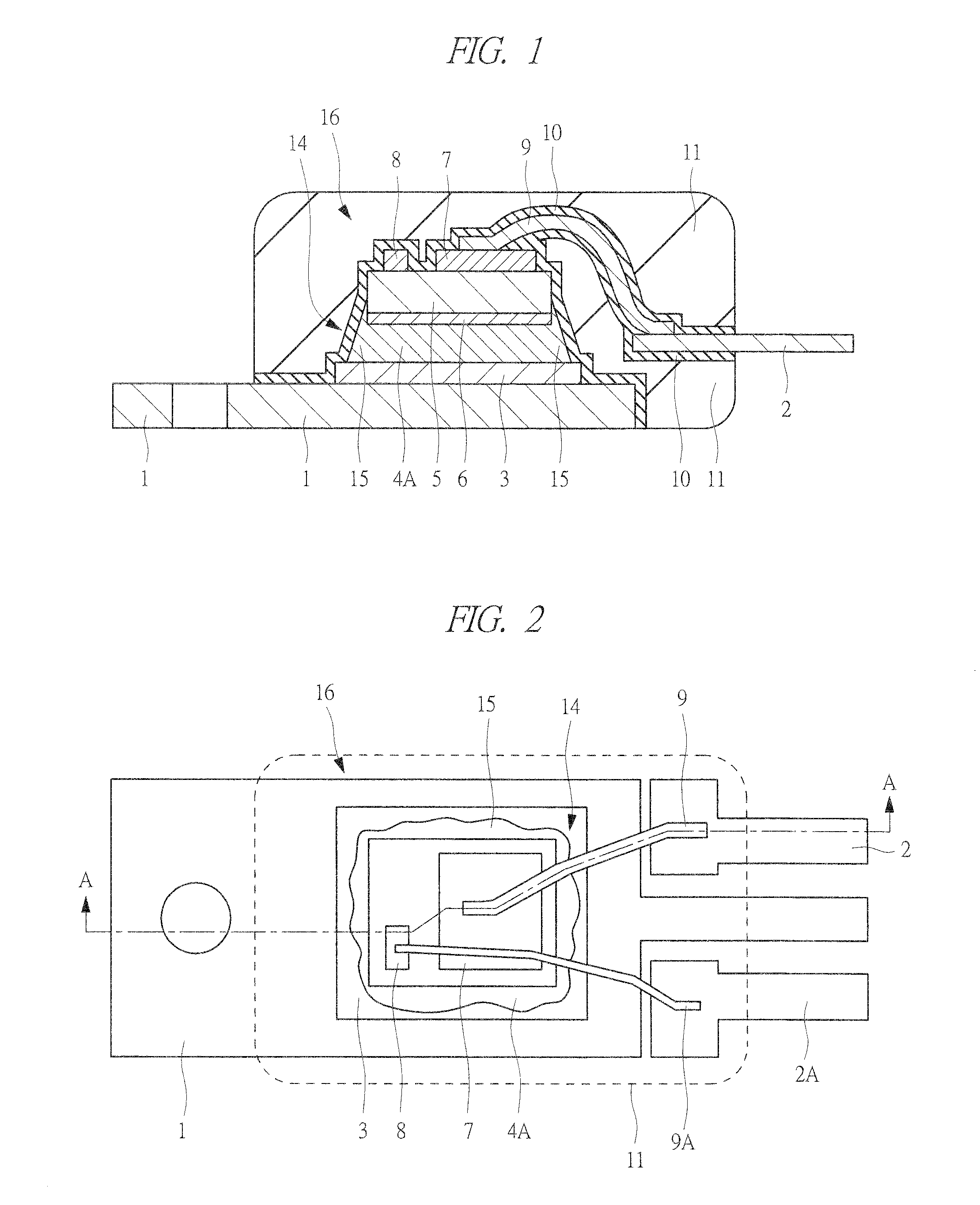
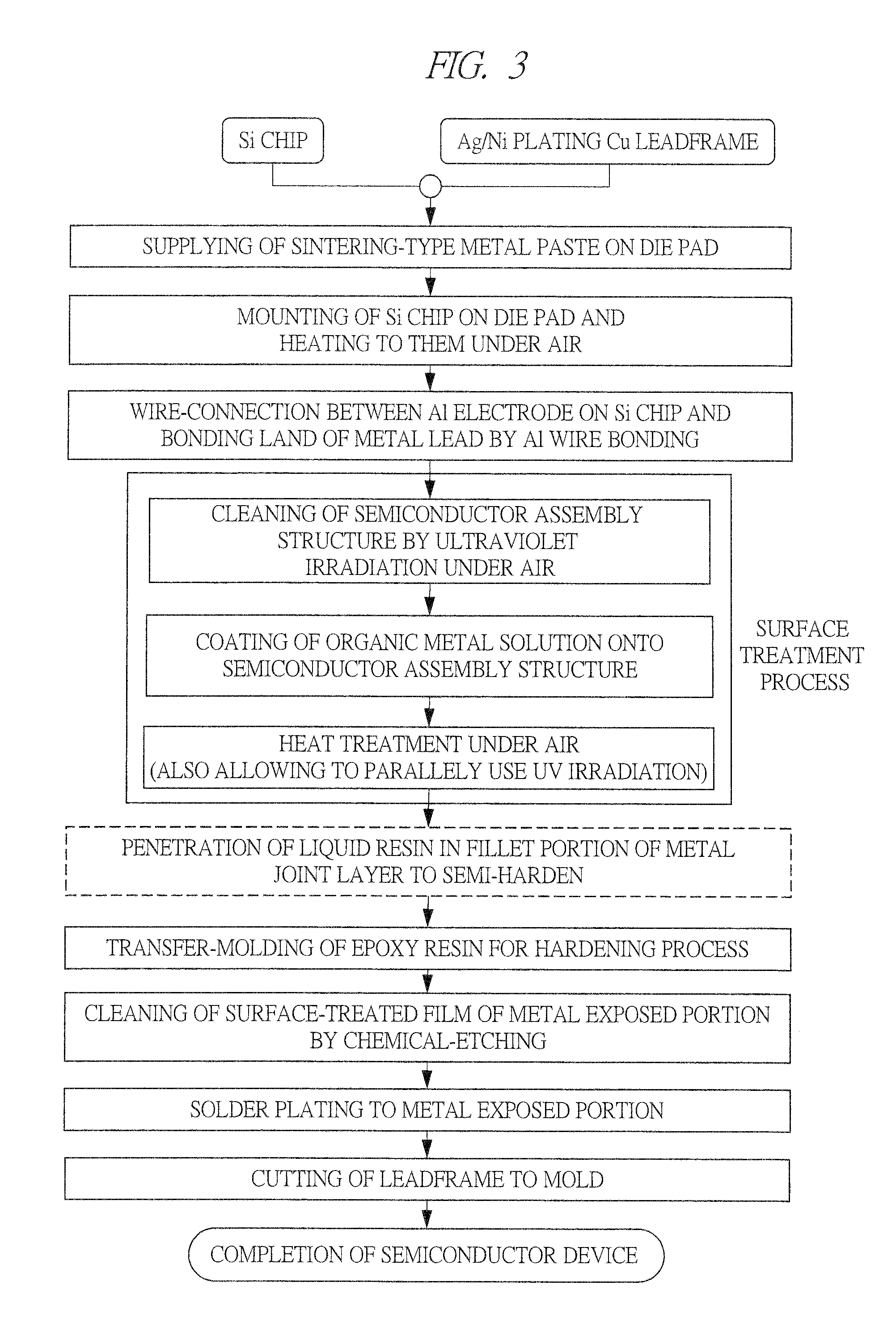
[0033]In the present embodiment, the present invention is applied to a method of manufacturing a semiconductor device, and the first embodiment will be described with reference to FIGS. 1 to 8.
[0034]FIGS. 1 and 2 illustrate a structure of a semiconductor device according to the present embodiment. FIG. 1 illustrates a cross-sectional view taken along a line A-A in FIG. 2. FIG. 2 is a top-surface plan view of the semiconductor device according to the present embodiment. Note that, in FIG. 2, epoxy molding compounds 11 in FIG. 1 are illustrated by a dash line, and a film 10 is not illustrated.
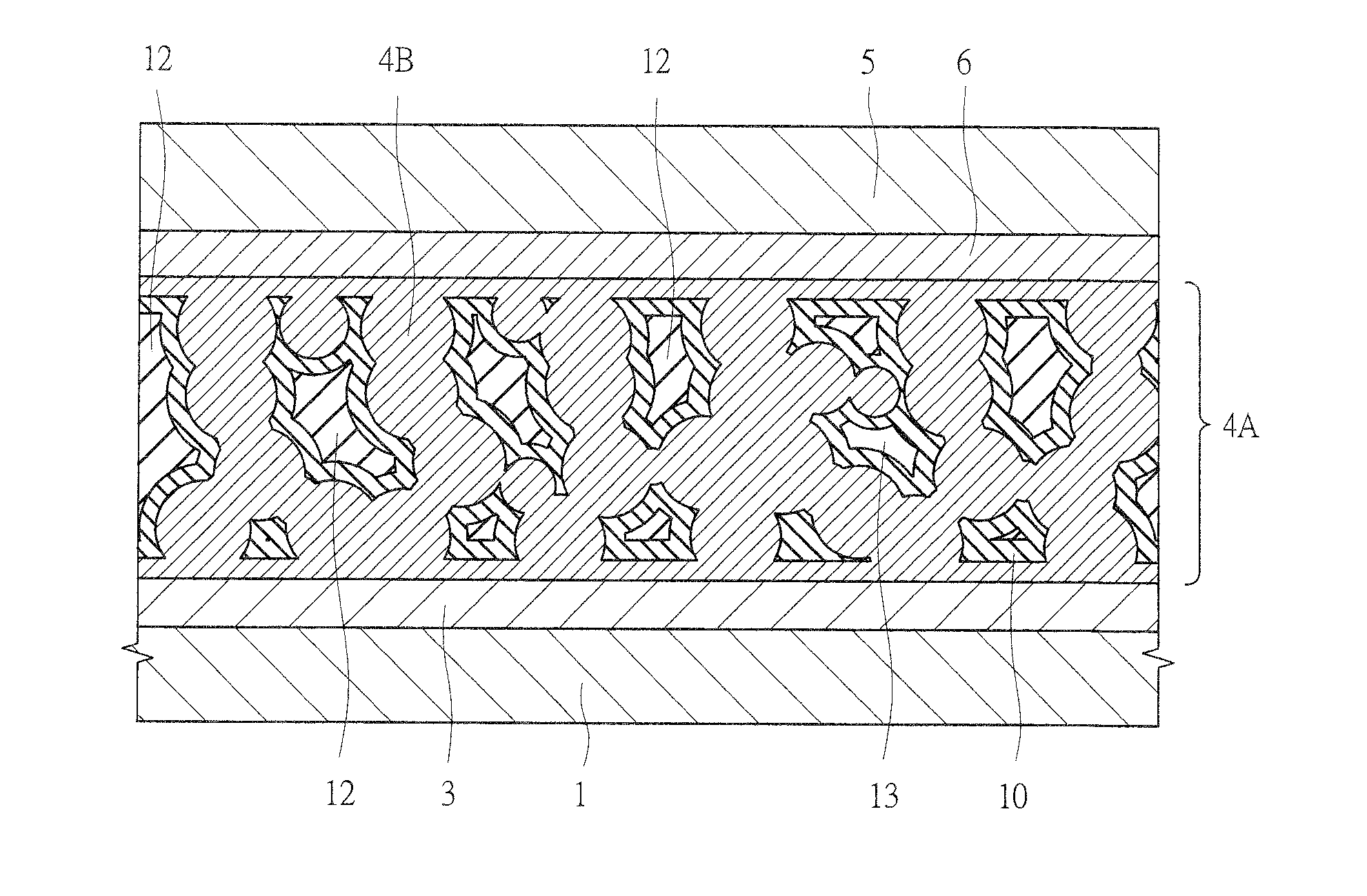
[0035]In FIGS. 1 and 2, a rear-surface electrode 6 made of a metal such as gold is formed on a rear surface of a Si (silicon) chip 5, which is a vertical semiconductor chip having an electrode on its rear surface like an IGBT and a power MOSFET, and a main electrode 7 and a control electrode 8 each formed of an Al (aluminum) film are formed on a main surface of the Si chip 5. An Ag (silver)-plati...
second embodiment
[0058]In the present embodiment, the present invention is applied to a method of manufacturing a semiconductor device, and the second embodiment will be described with reference to FIGS. 10 and 11.
[0059]FIGS. 10 and 11 illustrate a structure of a semiconductor device according to the present embodiment. FIG. 10 illustrates a cross-sectional view taken along a line B-B in FIG. 11. FIG. 11 illustrates a top-surface plan view of the semiconductor device according to the present embodiment. Note that, in FIG. 11, epoxy molding compounds 28 in FIG. 10 are illustrated by a dotted line, and a film 26 and an Ag-plating film 30 are not illustrated.
[0060]In FIGS. 10 and 11, a rear-surface electrode 20 made of a metal such as gold is formed on a rear surface of a Si chip 19 which is a vertical semiconductor chip, and a main electrode 22 in which Ni / Au is formed on an Al film and a control electrode 23 are formed on a main surface of the Si chip 19. An Ag-plating film 24 is formed on a surface ...
third embodiment
[0065]In the present embodiment, the present invention is applied to a method of manufacturing a semiconductor device, and the third embodiment will be described with reference to FIG. 12.
[0066]FIG. 12 illustrates a structure of a semiconductor device according to the present embodiment. In FIG. 12, a rear-surface electrode 41 made of a metal such as gold is formed on a rear surface of a Si chip 40 which is a vertical semiconductor chip, an Al film (not illustrated) is formed on a main surface of the Si chip 40, and a main electrode 43 made of Ni / Au and a control electrode not illustrated are formed on the Al film. An Ag-plating film 45 is formed on a chip-mounting surface of a metal leadframe 44, and the Si chip 40 is die-bonded onto the Ag-plating film 45 via an Ag porous joint layer 46 by metallic bond. A thickness of the joint layer 46 is 150 μm, and its porosity is 50%. An oxide film 47 mainly made of ZnO having a thickness of 10 to 100 nm is formed on a metal surface in the jo...
PUM
| Property | Measurement | Unit |
|---|---|---|
| thickness | aaaaa | aaaaa |
| diameter | aaaaa | aaaaa |
| diameter | aaaaa | aaaaa |
Abstract
Description
Claims
Application Information
 - R&D
- Intellectual Property
- Life Sciences
- Materials
- Tech Scout
- Unparalleled Data Quality
- Higher Quality Content
- 60% Fewer Hallucinations
Browse by: Latest US Patents, China's latest patents, Technical Efficacy Thesaurus, Application Domain, Technology Topic, Popular Technical Reports.
© 2025 PatSnap. All rights reserved.Legal|Privacy policy|Modern Slavery Act Transparency Statement|Sitemap|About US| Contact US: help@patsnap.com


