
Barrier film for flexible copper substrate and sputtering target for forming barrier film

a flexible copper substrate and barrier film technology, applied in the direction of vacuum evaporation coating, transportation and packaging, synthetic resin layered products, etc., can solve the problems of short circuit in the wiring on the circuit board, ineffectiveness, and barrier film peeling from the polyimide film, so as to prevent film peeling and achieve sufficient barrier effect, the effect of superior

Active Publication Date: 2012-11-27
JX NIPPON MINING & METALS CORP
View PDF29 Cites 0 Cited by
  • Summary
  • Abstract
  • Description
  • Claims
  • Application Information

AI Technical Summary

Benefits of technology

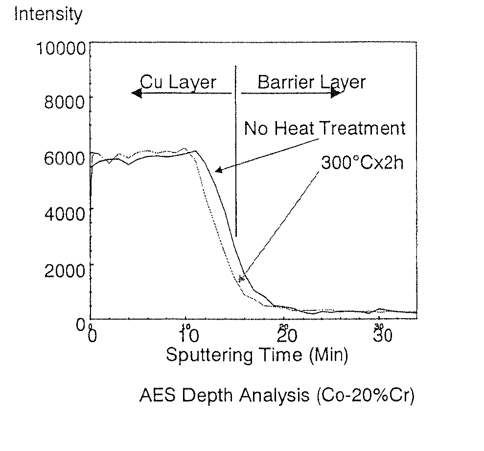
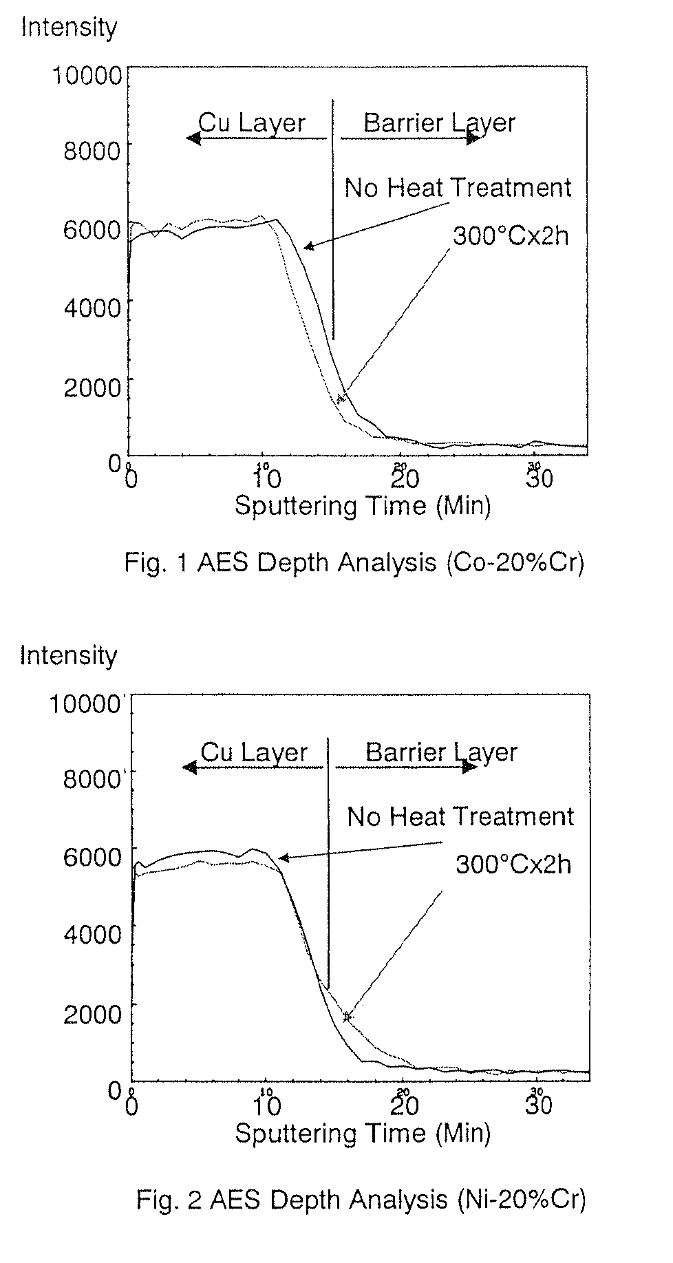
[0011]In light of the foregoing problems of conventional technology, an object of the present invention is to obtain a barrier film for a flexible copper substrate and a sputtering target for forming such barrier film. The barrier film for a flexible copper substrate can inhibit the diffusion of copper to a resin film such as polyimide. Further, the film thickness is thin enough to prevent film peeling, and is capable of obtaining a sufficient barrier effect even in a minute wiring pitch. Moreover, the barrier characteristics will not change even when the temperature rises due to heat treatment or the like.
[0012]As a result of intense study, the present inventors discovered that the foregoing problems can be overcome by using an alloy having effective barrier characteristics, forming the barrier film as thin as possible in order to prevent peeling, and improving the uniformity of the deposited film.
[0014]The barrier film for a flexible copper substrate of the present invention yields superior effects in that it has a film thickness that is thin enough to prevent film peeling, is capable of obtaining a sufficient barrier effect even in a minute wiring pitch, and has barrier characteristics that will not change even when the temperature rises due to heat treatment or the like. The present invention yields significant characteristics in that it is capable of effectively inhibiting the diffusion of copper to a resin film such as polyimide.

Problems solved by technology

The problem here is that the copper formed on the polyimide film easily diffuses (migrates) in the polyimide film, and causes a short circuit in the wiring on the circuit board.
In addition, when the wiring pitch becomes narrower than 30 μm, it is not possible to prevent diffusion to the polyimide layer with a conventional barrier layer, and it has become known that this is not necessarily effective.
Nevertheless, when the thickness exceeds a certain value, another problem occurs in that the barrier film would peel from the polyimide film.
Therefore, this method was insufficient to become a fundamental solution.
Nevertheless, in this case, since the foregoing method does not fundamentally solve the diffusion of the barrier metal, this problem still needs to be solved.

Method used


Image

  • Barrier film for flexible copper substrate and sputtering target for forming barrier film
  • Barrier film for flexible copper substrate and sputtering target for forming barrier film

Examples


example 1

[0033]The composition of Co-20 wt % Cr was subject to melting and casting to prepare a Co—Cr ingot. This ingot was subject to hot forging and hot rolling at 1100° C., cooled, and thereafter subject to heat treatment at 500° C. for 2 hours and machined into a target. The grain size of this target was 280 μm. This target was further subject to finishing so that the average surface roughness Ra became 0.14 μm.

[0034]The Cr concentration of the target was 19.1 wt %, impurity components were 0.2 ppm of Na, 0.1 ppm of K, 0.02 ppm of U, 0.03 ppm of Th, the total content of metal components was 470 ppm, and the oxygen content was 10 ppm.

[0035]This target was bonded to the backing plate with indium, and the target side and the backing plate near the target were subject to bead blasting and coarsened until the Ra became 7.5 μm.

[0036]This target was used to prepare a barrier layer having a film thickness of 140 nm. As a result of analyzing the composition of the respective added components of t...

example 2 to 8

[0047]A target was prepared with the same manufacturing method as Example 1, and such target having an alloy composition and relative magnetic permeability within the range of the present invention shown in Table 1 was used to form a barrier layer having a film thickness of 10 nm on a polyimide sheet having a thickness of 38 μm.

[0048]Further, the composition (wt %) of the respective added components of the barrier layer, the film thickness (nm) of the barrier layer, the film thickness uniformity (%) that measured the film thickness of the barrier layer at a 49-point, and the endurance test (hours) are similarly shown in Table 1. The film composition (wt %), film thickness (nm), and film thickness uniformity (%) of the barrier film of Examples 2 to 8 were all within the range of the present invention.

[0049]Further, a 20 nm Cu seed layer was deposited on this barrier layer with sputtering, and this was further subject to electroplating so as to form a Cu layer of 8 μm. An endurance te...


PUM

PropertyMeasurementUnit
grain sizeaaaaaaaaaa
average roughnessaaaaaaaaaa
grain sizeaaaaaaaaaa

Abstract

A barrier film for a flexible copper substrate comprising a Co—Cr alloy film containing 5 to 30 wt % of Cr and a balance of unavoidable impurities and Co is provided. The barrier film has a thickness of 3 to 150 nm and a film thickness uniformity of 10% or less at 1σ. A sputtering target for forming a barrier film comprising a Co—Cr alloy containing 5 to 30 wt % of Cr and a balance of unavoidable impurities and Co is also provided. The relative magnetic permeability in the in-plane direction of the sputtered face of the target is 100 or less. The barrier film for a flexible copper substrate and the sputtering target for forming such barrier film have a film thickness that is thin enough to prevent film peeling and inhibiting the diffusion of copper to a resin film such as polyimide, is capable of obtaining a sufficient barrier effect even in a minute wiring pitch and has barrier characteristics that will not change even when the temperature rises due to heat treatment or the like.

Description

CROSS REFERENCE TO RELATED APPLICATIONS[0001]This application is a divisional of co-pending U.S. application Ser. No. 11 / 573,167, which is the National Stage of International Application No. PCT / JP2005 / 013548, filed Jul. 25, 2005, which claims the benefit under 35 USC §119 of Japanese Application No. 2004-232872, filed Aug. 10, 2004.BACKGROUND OF THE INVENTION[0002]The present invention relates to a barrier film for a flexible copper substrate and a sputtering target for forming such barrier film capable of effectively inhibiting the diffusion of copper to a resin film such as polyimide.[0003]Conventionally, a copper layer is formed on a resin film such as polyimide, which is to become the base film, upon manufacturing a flexible copper substrate. Specifically, a copper seed layer is formed on the polyimide film by sputtering or electroless deposition, and a thick copper plated layer is formed thereon. Thereafter, the copper is subject to etching so as to form a copper circuit patte...

Claims


Application Information

Patent Timeline
Patent Type & Authority Patents(United States)
IPC IPC(8): B32B15/08B32B27/06B32B15/01B32B15/00B32B5/10B32B15/20B32B27/00
CPCC22C19/07C23C14/205C23C14/3414H05K3/388H05K1/0346H05K1/0393Y10T428/1291Y10T428/31681Y10T428/31721Y10T428/12569Y10T428/12847Y10T428/12715
Inventor IRUMATA, SHUICHIYAMAKOSHI, YASUHIRO
Owner JX NIPPON MINING & METALS CORP
Learn More