Organic luminescent materials, coating solution using same for organic emitting layer, organic light emitting device using coating solution and light source device using organic light emitting device

a luminescent material and organic technology, applied in thermoelectric devices, energy-saving lighting, sustainable buildings, etc., can solve the problems of difficulty in controlling the concentration of dopant in the coating method of producing an organic light-emitting device, and difficulty in emitted white color, so as to achieve easy control of the concentration of dopant and easy emitted white light

Inactive Publication Date: 2012-11-27
HITACHI LTD
View PDF6 Cites 36 Cited by
  • Summary
  • Abstract
  • Description
  • Claims
  • Application Information

AI Technical Summary

Benefits of technology

[0021]The present invention provides an organic luminescent material capable of emitting white light, produced by easily controlling dopant concentrations, coating solution using the organic luminescent material for organic light-emitting layers, organic light-emitting device using the coating solution and light source device using the organic light-emitting device. The other challenges, structures and advantages will be clarified by the description of the preferred embodiments described below.
[0022]The present invention also provides an organic luminescent material capable of easily emitting white light, coating solution using the organic luminescent material for organic light-emitting layers, organic light-emitting device using the coating solution and light source device using the organic light-emitting device.

Problems solved by technology

The conventional method for producing an organic light-emitting device involves a disadvantage of difficulty in emitting white color by easily controlling red-, green- and blue-light-emitting dopant concentrations without causing their phase separation.
The conventional coating method for producing an organic light-emitting device involves a disadvantage of difficulty in controlling dopant concentrations because of their very low concentrations, about 0.02% by mol with a green-light-emitting dopant, 0.02% and 0.015% by mol with a red-light-emitting dopant.

Method used


Image

  • Organic luminescent materials, coating solution using same for organic emitting layer, organic light emitting device using coating solution and light source device using organic light emitting device
  • Organic luminescent materials, coating solution using same for organic emitting layer, organic light emitting device using coating solution and light source device using organic light emitting device
  • Organic luminescent materials, coating solution using same for organic emitting layer, organic light emitting device using coating solution and light source device using organic light emitting device

Examples


example 1

Synthesis of Exemplary Compound 1

[0055]First, the red-light-emitting dopant represented by the structural formula (1) was synthesized as one of the major constituents of the present invention to produce the white-light-emitting device of the present invention.

[0056]The compound represented by Formula 6 was synthesized as the essential intermediate for synthesizing the compounds represented by Formulae 2 and 3 by the following procedure.

[0057]

[0058]A 200 mL three-necked flask was charged with 0.718 g of phenylisoquinoline dissolved in 30 mL of ethoxyethanol and 0.418 g of iridium chloride dissolved in 10 mL of water, which were mixed with each other in the flask. The mixture was heated at 120° C. for 10 hours under reflux in a nitrogen atmosphere, then cooled to room temperature, and treated by evaporation. The resulting solid was washed with alcohol to produce the compound represented by Formula 6.

(Synthesis of Compound Represented by Formula 2)

[0059]The compound represented by Form...

example 2

[0068]Example 2 prepared the light-emitting layer in the same manner as in Example 1, except that mCP was used for the host material, bis(3,5-difluoro-2-(2-pyridyl)phenyl-(2-carboxypyridyl) iridium (III) was used for the blue-light-emitting dopant, the compound represented by Formula 2 was used for the red-light-emitting dopant, and the compound represented by Formula 5 or Ir(ppy)3 dissolved in THF was used for the green-light-emitting dopant.

[0069]

[0070]A voltage was applied to the organic white-light-emitting device with the green-light-emitting dopant of the compound represented by Formula 5 to confirm that each of the red-light-emitting dopant, green-light-emitting and blue-light-emitting dopants emitted light. For the device with the green-light-emitting dopant of Ir(ppy)3, the blue-light-emitting and green-light-emitting dopants emitted light of lower intensity than the red-light-emitting dopant.

example 3

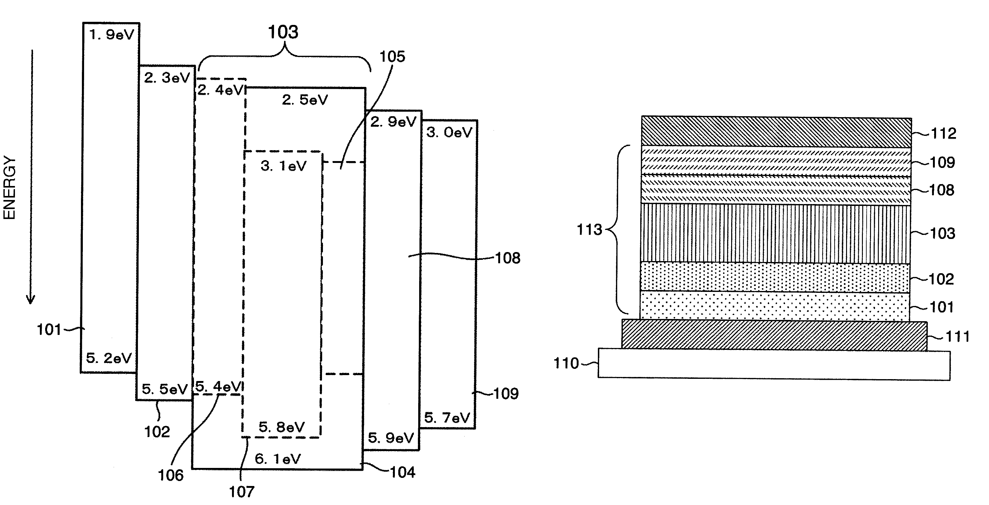
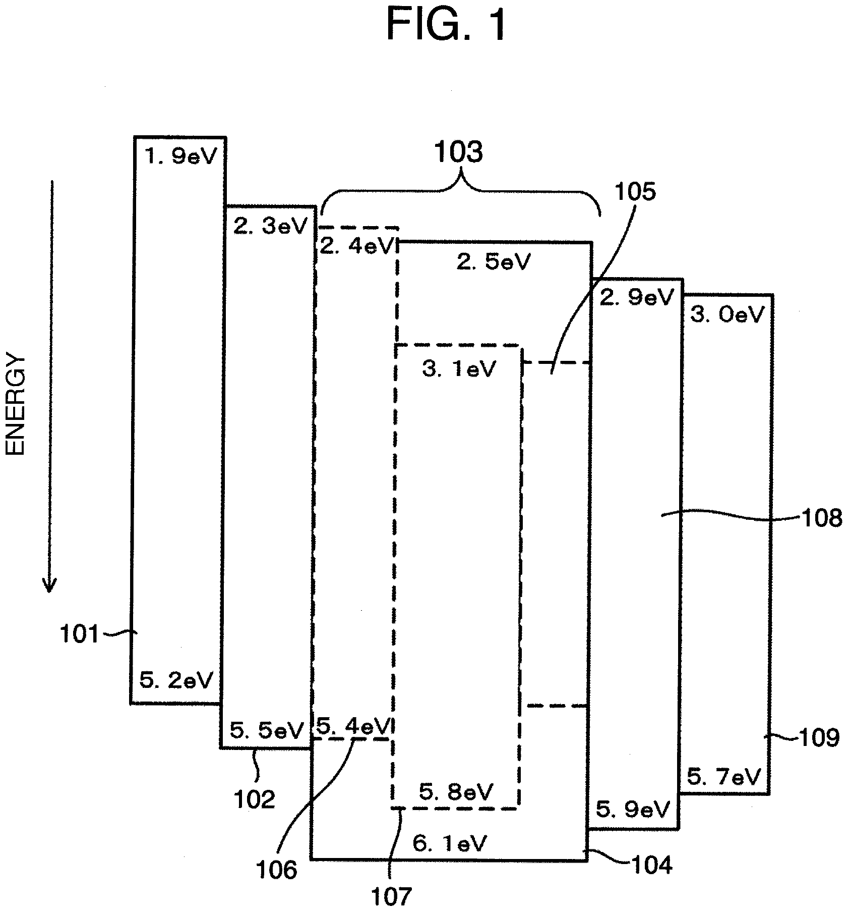
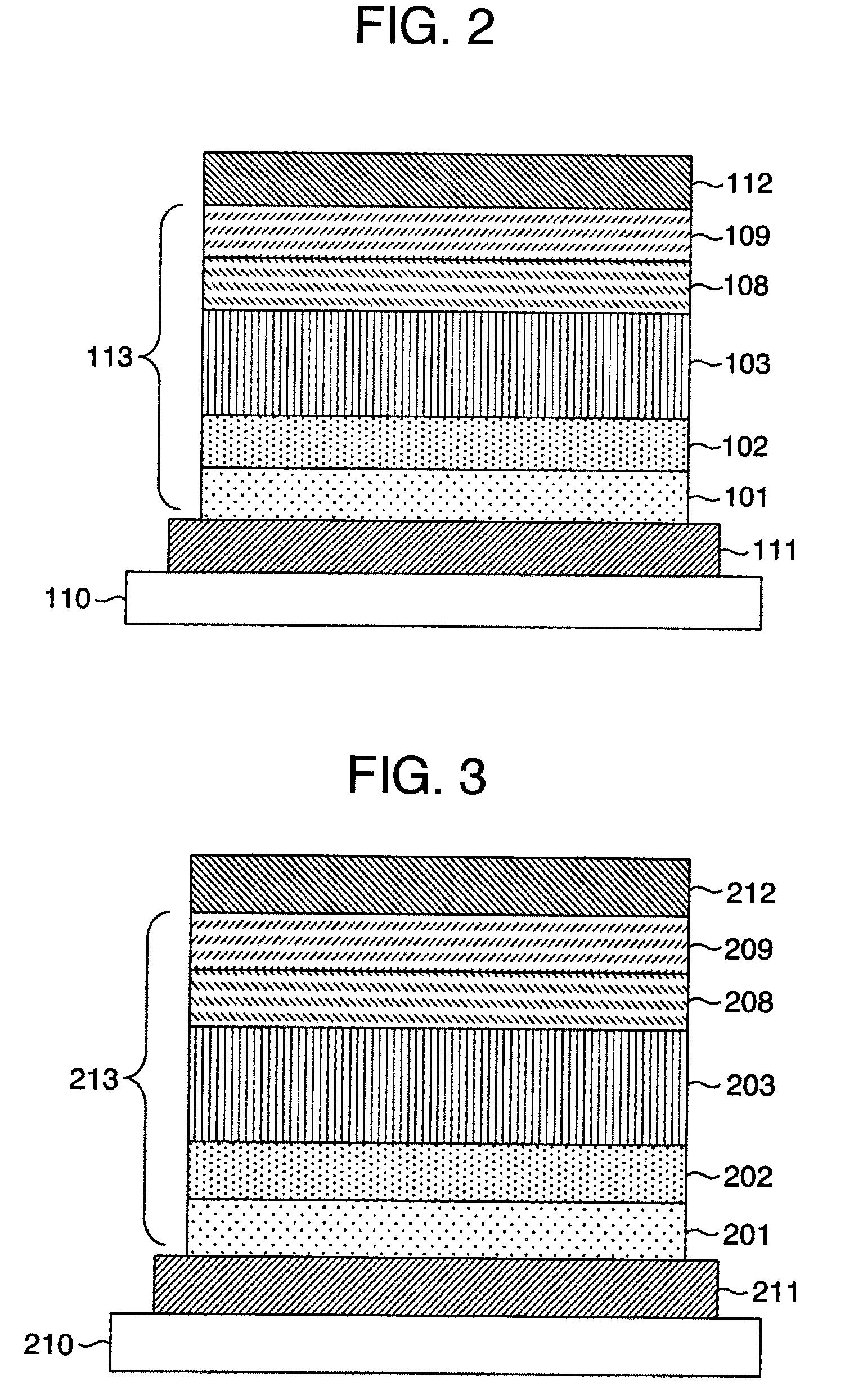
[0071]FIG. 3 is a cross-sectional view of the organic white-light-emitting device prepared in Example 3. The device had an upper electrode 212 as the first electrode, lower electrode 211 as the second electrode and organic layer 213. The lower electrode 211 and upper electrode 212 may be used as the respective first and second electrodes. The device illustrated in FIG. 3 comprised a substrate 210 which supported the lower electrode 211, organic layer 213 and upper electrode 212 in this order from the substrate. It was of bottom emission type in which light emitted by a light-emitting layer 203 was taken out from the lower electrode 211 side. The lower electrode 211 was the transparent electrode working as the anode and upper electrode 212 was the repeller working as the cathode. The organic layer 213 was composed of a hole injection layer 210, hole transport layer 202, light-emitting layer 203, electron transport layer 208 and electron injection layer 209. The organic layer 213 may ...


PUM


Abstract

It is an object of the present invention to provide an organic light-emitting device which can emit white light by easily controlling dopant concentrations. The organic light-emitting device has a first electrode (112) and second electrode (111) which hold a light-emitting layer (113) in-between, wherein the light-emitting layer contains a host material (104), red-light-emitting dopant (105), green-light-emitting dopant (106) and blue-light-emitting dopant (107), the red-light-emitting dopant containing a first functional group for transferring the dopant toward the first electrode and the green-light-emitting dopant containing a second functional group for transferring the dopant toward the second electrode.

Description

FIELD OF THE INVENTION[0001]The present invention relates to an organic luminescent material, coating solution using the organic luminescent material for organic light-emitting layers, organic light-emitting device using the coating solution and light source device using the organic light-emitting device.BACKGROUND OF THE INVENTION[0002]The methods for producing organic light-emitting devices (LEDs) broadly fall into two categories, vacuum vapor deposition and coating. The coating method has advantages of easily producing large-area films and high material utilization factor. In order to apply the coating method, development of devices with a single light-emitting layer is demanded, because it is necessary to reduce number of organic LED layers.[0003]For organic white-light-emitting devices with a single light-emitting layer, Patent Document 1 discloses an organic EL device with a single light-emitting layer of a composition of at least (a) polymer and (b) compound for forming a lig...

Claims


Application Information

Patent Timeline
Patent Type & Authority Patents(United States)
IPC IPC(8): H01L51/54
CPCC09K11/06H01L51/56H01L51/5028H01L51/0002H05B33/14C09K2211/1011C09K2211/1029C09K2211/185Y02B20/181H01L51/5036H10K50/121H10K50/12H10K50/125Y02B20/00H10K71/00H10K71/10
Inventor SAKUMA, HIROTAKAARATANI, SUKEKAZUSASAKI, HIROSHI
Owner HITACHI LTD
Why Eureka
Try Eureka