Ferrite powder and its production method

a technology of ferrite powder and slurry, applied in the field of ferrite powder, can solve the problems of reducing slurry, deteriorating formability, and reducing production yield, and achieve the effects of favorable flowability of ferrite slurry, small thickness, and small siz

Inactive Publication Date: 2013-01-01
NGK INSULATORS LTD
View PDF4 Cites 0 Cited by
  • Summary
  • Abstract
  • Description
  • Claims
  • Application Information

AI Technical Summary

Benefits of technology

[0008]For instance, a preferred power inductor is the one structured by a Ni—Zn—Cu-based ferrite sintered body containing a spiral Ag-conductor. To produce the power inductor, it is necessary to sinter a ferrite having a single phase composition and having 100 or larger relative magnetic permeability. To do this, it is preferable that the grain diameter (median diameter, 50% diameter) of the ferrite powder is decreased while increasing the slurry concentration to improve the sinterability of the ferrite because poor sinterability decreases the sinter density to raise a problem of decreasing in the relative magnetic permeability.
[0023]At temperatures lower than the temperature of generating the ferrite single phase, not all the components react to become the ferrite, and unreacted substances are left behind. If the powder is calcined at a temperature of lower than 30° C. below the temperature of generating the ferrite single phase, the quantity of unreacted substances becomes small, and the magnetism of the powder increases. As a result, the viscosity of ferrite slurry becomes 3000 cps or larger. On the other hand, when the powder is calcined at a temperature lower than 200° C. below the temperature of generating the ferrite single phase, the quantity of unreacted substances increases to worsen the sinterability and significantly deteriorates the relative magnetic permeability, though the viscosity of ferrite slurry decreases. If, however, calcination is conducted at temperatures lower by 30° C. to 200° C. than the temperature of generating the ferrite single phase (or the temperatures lower by 30° C. to 200° C. than the basis temperature of generating the ferrite single phase), that problem can be avoided, and the viscosity of ferrite slurry becomes low to be applicable to gel casting, and further favorable sinterability is attained to produce a sintered body having high relative magnetic permeability. If the calcination is done at temperatures lower by 50° C. to 130° C. than the temperature of generating ferrite single phase, the viscosity of ferrite slurry becomes 1000 cps or smaller, thus obtaining a ferrite sintered body having further high relative magnetic permeability.
[0031]The ferrite slurry according to the present invention contains the ferrite powder of the present invention, has excellent dispersibility, and has high concentration and low viscosity, thus the ferrite slurry shows excellent flowability, easily pours into the mold, and provides a green body of good sinterability. As a result, the ferrite slurry of the present invention provides a homogeneous ferrite sintered body generating very few cracks through forming and firing thereof. In particular, when the ferrite powder has a concentration of from 35 to 60% by volume and has a viscosity of from 50 to 3000 cps, preferably 1000 cps or smaller, gel casting can provide an excellent ferrite sintered body generating no cracks.
[0032]The method for producing ferrite powder according to the present invention provides a ferrite powder by: calcining a powder containing a main raw material having Fe2O3 and a metal oxide of at least one of Ni oxide, Zn oxide, and Cu oxide at a temperature lower by 30° C. to 200° C. than the temperature of generating a ferrite single phase, thus preparing a calcined powder; and then milling the calcined powder. As a result, the obtained ferrite powder contains unreacted substances, and shows small magnetism. That is, the method for producing ferrite powder according to the present invention is effective to produce the ferrite powder of the present invention.
[0034]The first method for producing inductor according to the present invention comprises the steps of: placing a spiral conductor in a mold; preparing any of the ferrite powders of the present invention using any of the methods for producing ferrite powder of the present invention; preparing a ferrite slurry using and processing the ferrite powder; pouring the ferrite slurry into a mold; solidifying the poured ferrite slurry around the conductor to obtain a green body; and firing the green body at a temperature ranging from 850° C. to 1100° C. Consequently, there can be obtained an inductor having thick conductor, for example, 50 μm or larger, having narrow distance between conductors, for example, 10 μm or smaller, and being completely sintered to give the intrinsic magnetism. This is because the flowability of the ferrite slurry is favorable, thus the ferrite slurry is at a high concentration, and because the ferrite slurry can be filled around the conductors without gap therearound even when the distance between the spiral conductors is narrow. That type of inductor is suitable as a power inductor of small size, small thickness, and low resistance (low loss). The method for producing inductor of the present invention provides a power inductor with reduced resistance of material by 40% or more compared with that of conventional materials. Similar effect is attained even by the second method for producing inductor of the present invention.

Problems solved by technology

On producing power inductor by gel casting, however, if the ferrite slurry as the core material of the power inductor is not a suitable one, there arises a problem that cracks are likely generated in the sintered ferrite body (power inductor) obtained by firing the green body prepared by gel casting, thus the production yield decrease.
It is therefore speculated that when these needs are satisfied, the flowability of slurry decreases and the formability deteriorates, thus likely generating cracks after firing.
When, however, the slurry is prepared using a powder having that small median diameter, the slurry viscosity increases to 10000 cps or larger, resulting in poor flowability and faulty pouring of the slurry into the mold to worsen the formability.

Method used


Image

  • Ferrite powder and its production method
  • Ferrite powder and its production method
  • Ferrite powder and its production method

Examples


example 1

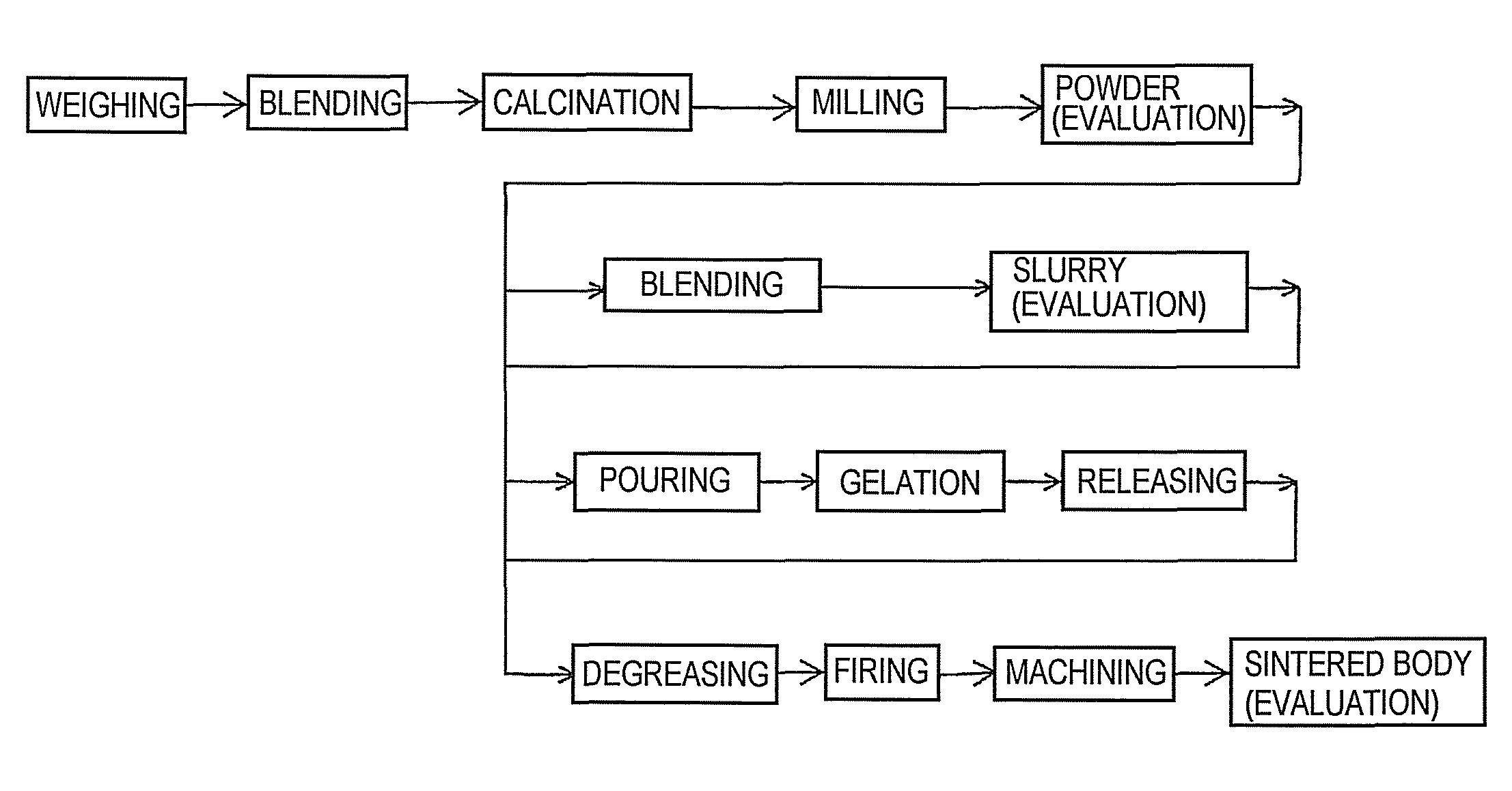
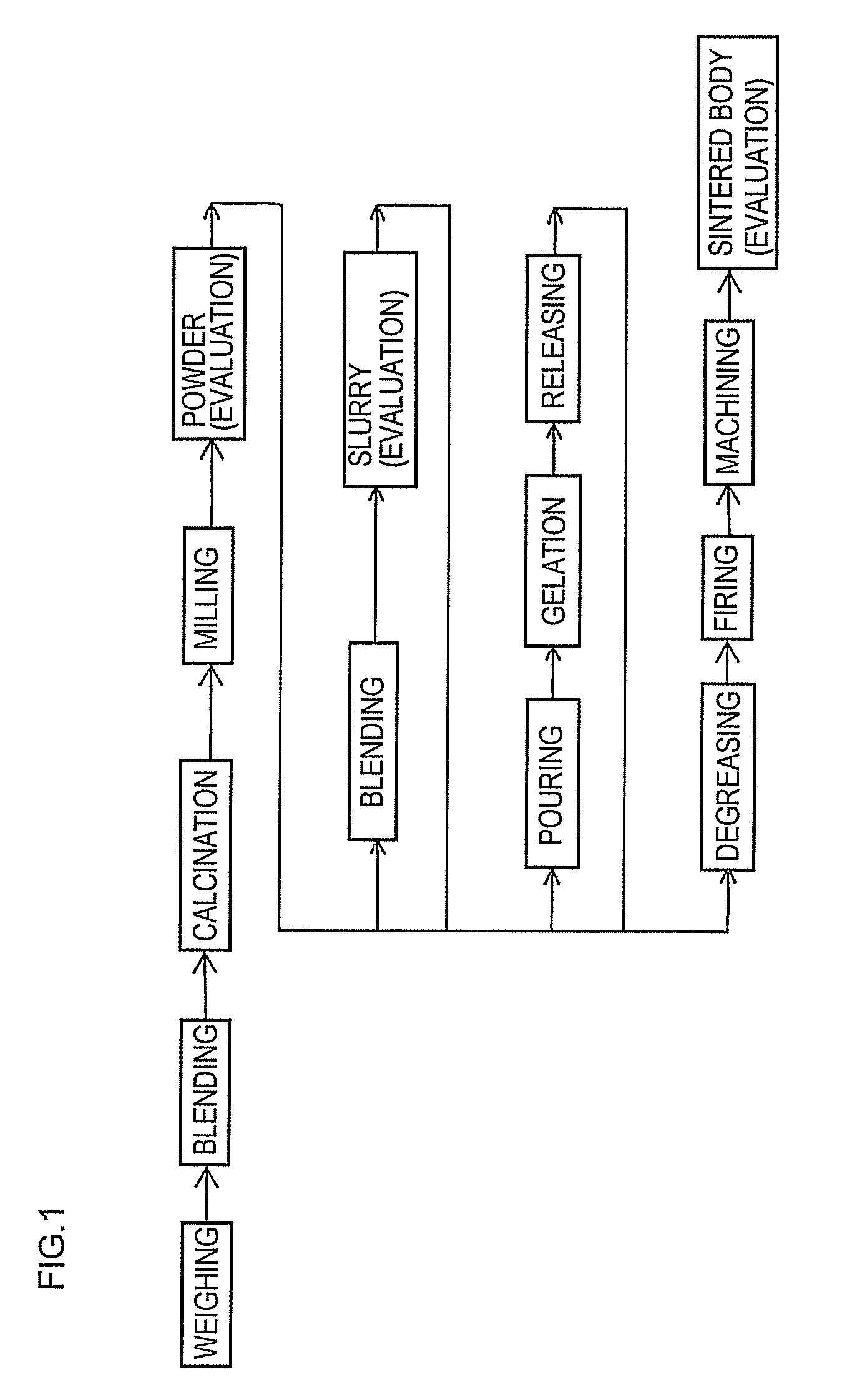
Preparation of Ferrite Powder

[0074]Individual raw material powders were weighed: Fe2O3 (0.5 μm) to 47.6% by mole, ZnO (0.3 μm) to 27.0% by mole, NiO (1 μm) to 16.3% by mole, and CuO (2 μm) to 9.1% by mole. These powders were put in a poly container together with zirconia balls and ion-exchange water. Using the ball-mill method, wet blending of them was given for 5 hours (blending time of raw material powders on producing the ferrite powder), thus obtained the slurry. The slurry was then dried in a dryer at 100° C., followed by sieving to obtain an intermediate powder (blended raw material powder). The composition gave 830° C. of the ferrite single-phasing temperature.

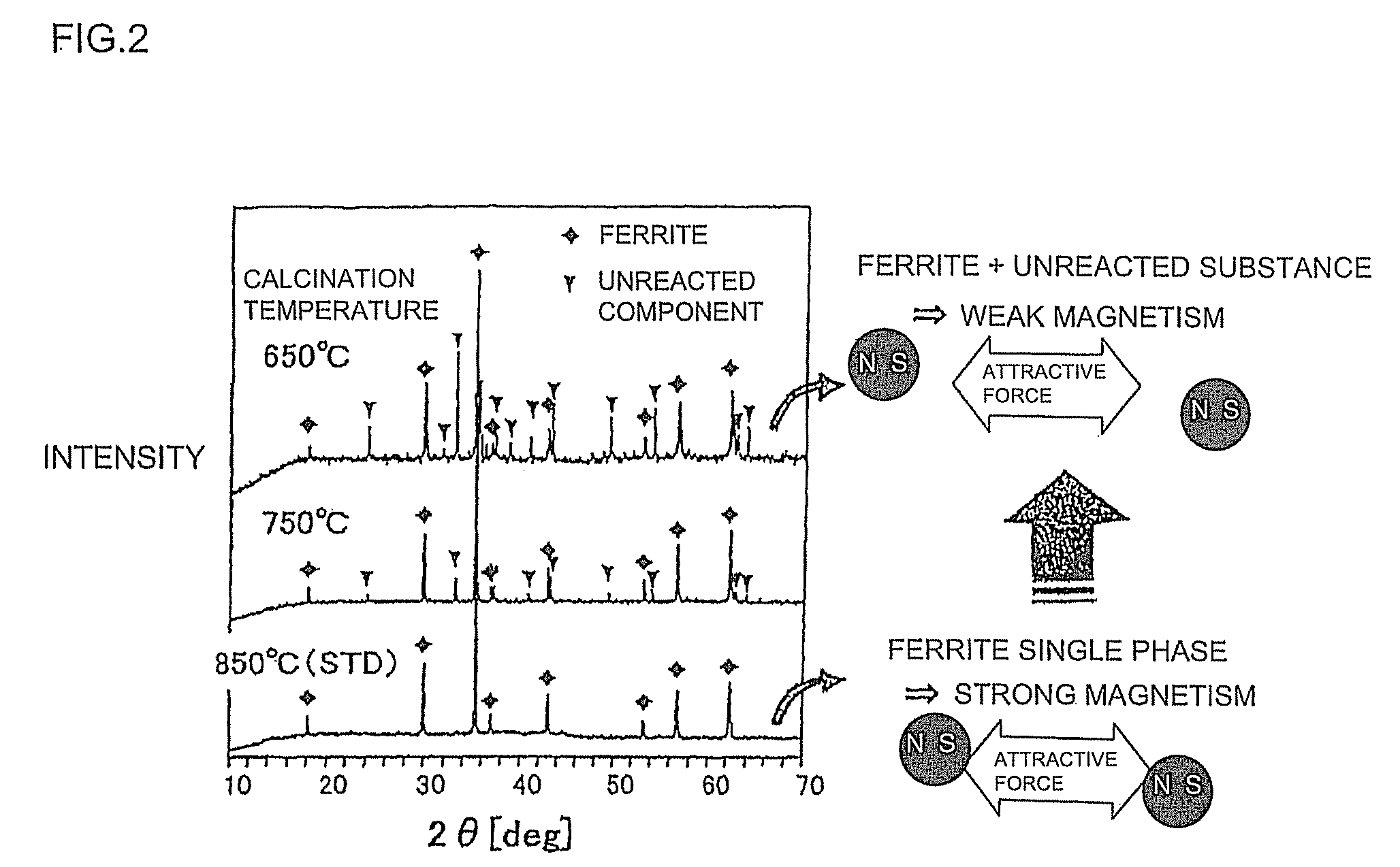
[0075]Next, the intermediate powder was calcined at 700° C. (the calcination temperature on producing the ferrite powder) for 2 hours, thus obtained a calcined powder. At that time, the temperature increase and decrease rate was set to 200° C. / h.

[0076]Then, thus obtained calcined powder was put in a poly container toget...

examples 2 to 25

, Comparative Examples 1 to 13

[0087]There were varied the median diameter and the specific surface area, the degree of spinel formation, and the remanent magnetization of ferrite powder through the adjustment of calcination temperature on producing the ferrite powder, and the mixing time of raw material powders and the milling time of calcined powder on producing the ferrite powder. In addition, similar to Example 1, there were prepared and evaluated the Ni—Zn—Cu-based ferrite powder, the ferrite slurry, and the ferrite sintered body. The specific surface area of mixed powder after mixing was in a range from 3.5 to 6.0 m2 / g, and the specific surface area of milled powder after milling was in a range from 2.5 to 5.5 m2 / g.

[0088]Table 1 shows the result of similar articles to those in Example 1. The evaluation criteria for Examples 2 to 25 and Comparative Examples 1 to 13 were the same to those of Example 1. For Example 6, Example 8, and Comparative Example 4, the remanent magnetizatio...


PUM

PropertyMeasurementUnit
median diameter D50aaaaaaaaaa
temperatureaaaaaaaaaa
specific surface areaaaaaaaaaaa

Abstract

A ferrite powder for producing a ferrite sintered body is provided, the ferrite powder having a median diameter D50 [μm] in a range from 0.1 to 0.8 μm, a degree of spinel formation in a range from 45 to 90%, and a remanent magnetization Br per unit mass [emu / g] satisfying the following formula after application of the maximum magnetic field of 15 kOe: 0.05≦Br≦2.0(ln.D50)+6.3. This ferrite powder produces a homogeneous ferrite sintered body having very few cracks by gel casting.

Description

FIELD OF THE INVENTION AND RELATED BACKGROUND OF THE INVENTION[0001]The present invention relates to a ferrite powder suitable for forming thereof by the gel-cast method, and to a method for producing same.BACKGROUND OF THE INVENTION[0002]Mobile devices such as cellphones enhanced the trend of weight-reduction and functional multiplication, thus they have become essential tools in everyday living. Accordingly, the electric and electronic components of these mobile devices progress in their development focusing on the technological targets of reduction in size, reduction in thickness, reduction in power-consumption, and of increase in the operating speed. These mobile devices are base parts along with resistors and capacitors. The development trend is the same in power inductors applied to voltage-conversion circuits.[0003]The power inductors are grouped into the coil type, the thin-film type, and the laminated type depending on the structure. Many of them have a core of ferrite and ...

Claims


Application Information

Patent Timeline
Patent Type & Authority Patents(United States)
IPC IPC(8): H01F17/00C04B35/26H01F41/04
CPCC01G49/0018C04B35/265C04B35/6263C04B35/62675C04B35/632H01F1/344H01F1/36C01G49/0063H01F41/0246C01P2002/32C01P2002/72C01P2004/62C01P2006/12C01P2006/42C04B2235/3279C04B2235/3281C04B2235/3284C04B2235/5409C04B2235/5436C04B2235/5445C04B2235/6023C04B2235/6562C04B2235/6565C04B2235/763
Inventor KOBAYASHI, NOBUYUKIOZAWA, SHUICHISATO, KEI
Owner NGK INSULATORS LTD
Why Eureka
Try Eureka