
Delta retiming in logic simulation

a logic simulation and delta retiming technology, applied in the field of logic design simulation, can solve the problems of inherently inaccurate, unrecognized race conditions and glitches, and analog type simulators require a prohibitive amount of computation, so as to efficiently simulate the design and reduce the run time penalty

Active Publication Date: 2013-01-01
SIEMENS PROD LIFECYCLE MANAGEMENT SOFTWARE INC
View PDF16 Cites 7 Cited by
  • Summary
  • Abstract
  • Description
  • Claims
  • Application Information

AI Technical Summary

Benefits of technology

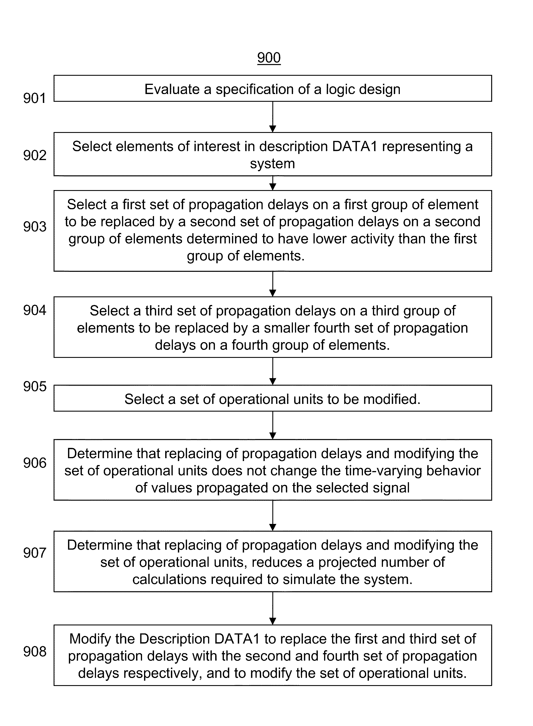
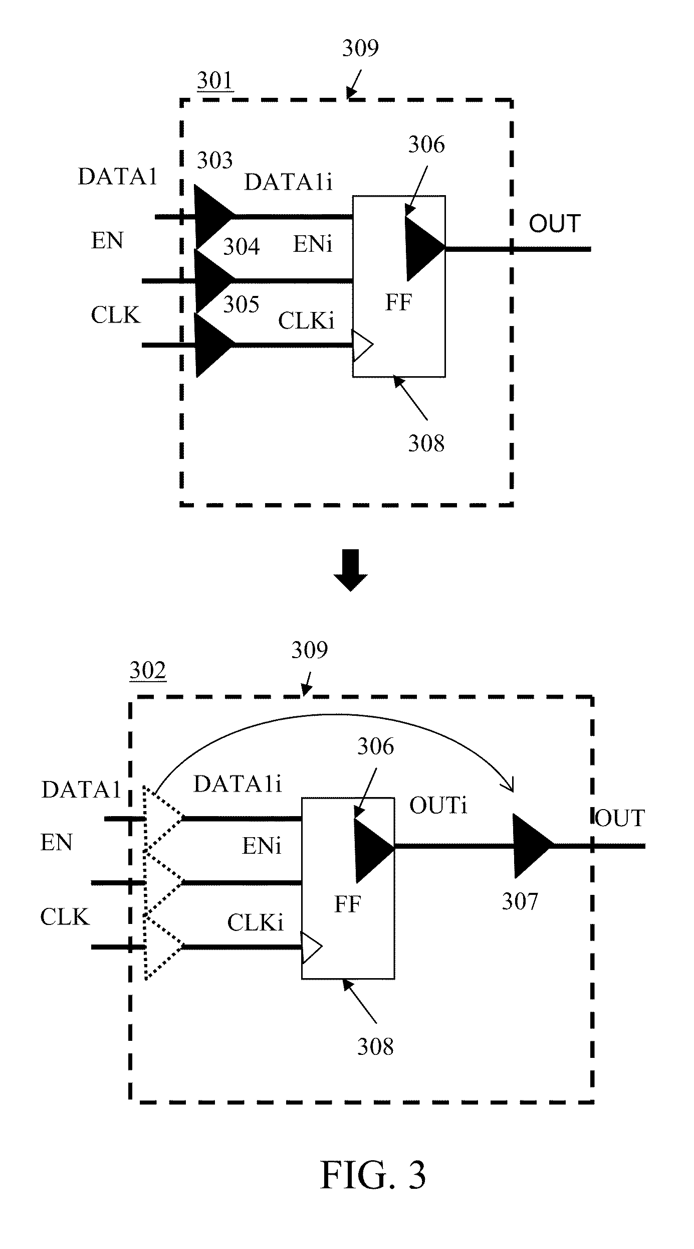
The patent describes a method for improving the performance of event-driven simulation of a logic design by using delta retiming. This helps to reduce the estimated number of delta cycles in the simulation and improves the efficiency of the simulation process. Delta retiming involves shifting delta delays from regions with high activity to regions with low activity, reducing the likelihood of new events being generated and queued for execution. Additionally, modifying elements to logically equivalent elements with reduced number of delta delays or reduced switching frequency of delta delays can also be employed for better performance. Overall, this method allows for improved speed and accuracy in simulating complex logic designs.

Problems solved by technology

While cycle based simulators are useful for initial logic design and are fast, they are inherently inaccurate and can lead to undetected race conditions and glitches which otherwise would have been caught by simulators that take into account propagation delays and real world factors such as clock skew.
However, analog type simulators require a prohibitive amount of computation to be useful in simulating most digital systems.
However, unlike analog simulators, event-driven simulators do not model every iteration of time, but calculate data only at events (e.g., at changes in the state of the system).
For many designs, event-driven simulation can still be time prohibitive.
However, it is often the case in these designs that the designer is only concerned with observing accurate simulation of a limited number of signals, like primary outputs and inputs or elements within the design.

Method used


Image

  • Delta retiming in logic simulation
  • Delta retiming in logic simulation
  • Delta retiming in logic simulation

Examples


Embodiment Construction

Operating Environment

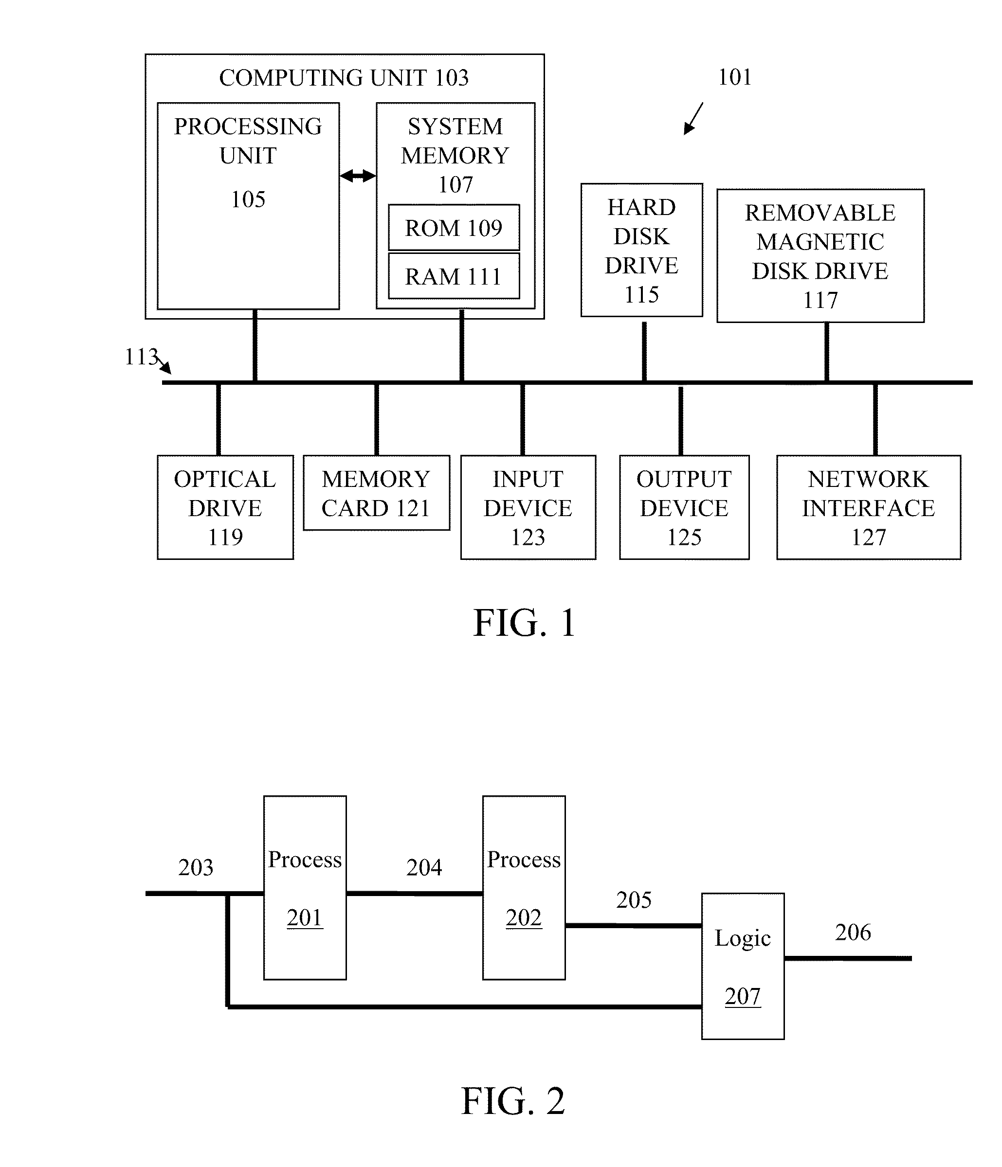
[0024]Various examples of the invention may be implemented through the execution of software instructions by a computing device, such as a programmable computer. Accordingly, FIG. 1 shows an illustrative example of a computing device 101. As seen in this figure, the computing device 101 includes a computing unit 103 with a processing unit 105 and a system memory 107. The processing unit 105 may be implemented with any of numerous types of devices, including but not limited to one or more general purpose microprocessors, one or more application specific integrated circuits, one or more field programmable gate arrays, and combinations thereof. The system memory 107 may include both a read-only memory (ROM) 109 and a random access memory (RAM) 111. As will be appreciated by those of ordinary skill in the art, both the read-only memory (ROM) 109 and the random access memory (RAM) 111 may store machine readable instructions (e.g., software, firmware, etc.) for execut...


PUM


Abstract

Aspects of the present invention are directed to improving the speed of event-driven simulation by manipulating delta delays in a system model to reduce delta cycle executions. The manipulation is performed in a manner that preserves delta cycle accurate timing on selected signals of the system, which may be of interest to a designer. Methods and systems are provided for identifying the signals of interest, and for determining portions of the design that may have delta delays retimed. Preserving the timing on the signals of interest ensures that race conditions and glitches present in the design on the signals of interest are still viewable by the designer. To reduce simulation time, delta delays may be moved from high activity signals to low activity signals, the total number of delta delays may be reduced, or a number of processes executed may be reduced.

Description

FIELD OF THE INVENTION[0001]Aspects of the present invention are directed generally to logic design simulation and more particularly to improving simulation speed by manipulating timing delays in a logic model to reduce delta cycle executions.BACKGROUND OF THE INVENTION[0002]In electronic design automation, simulators are used to autonomously interpret a system specification (e.g., a logic design model), and to simulate the behavior of the system over a simulated period of time. The system may be specified at various levels of detail and may include various elements. For example, a specification for a digital electronic circuit may be described at an algorithm level, at a register-transfer-level (RTL), or at a gate level.[0003]An algorithm level specification describes the relationship between a set of inputs to a set of outputs using a set of computations. At a more detailed register transfer level, the system is described in terms of interconnected combinatorial logic blocks and r...

Claims


Application Information

Patent Timeline
Patent Type & Authority Patents(United States)
IPC IPC(8): G06F17/50G06F9/455G06G7/62G06G7/54
CPCG06F17/5022G06F17/5009G06F30/33G06F30/20G06F30/3308
Inventor KAKKAR, SACHINRIES, JOHN
Owner SIEMENS PROD LIFECYCLE MANAGEMENT SOFTWARE INC
Learn More