Data communication circuit with equalization control

a data communication circuit and equalization control technology, applied in the field of data communication circuits, can solve the problems of deterioration of rx input signals, unreasonable bit error rates of data recovery on the receiver side, and worsening of above mentioned problems, so as to reduce power consumption and circuit area, increase the maximum achievable speed, and reduce power consumption

Active Publication Date: 2013-03-12
NXP BV
View PDF14 Cites 18 Cited by
  • Summary
  • Abstract
  • Description
  • Claims
  • Application Information

AI Technical Summary

Benefits of technology

[0018]In an embodiment a transition phase detector is used that comprises a sampling circuit for sampling the equalized signal at different phases during a symbol period and a comparator is used to compare pairs of sample values for successive phase positions. This provides for an all digital way of detecting the phase positions of transitions, which reduces power consumption and circuit area compared to (partly) analog solutions.
[0019]In a further embodiment the sampling circuit comprises a plurality of samplers, each for a respective one of the phase positions, each operated by respective clock signal with a period equal to the symbol period and a respective phase corresponding to respective ones of the phase positions. In this way no higher frequencies are needed than the symbol frequency. This increases the maximum achievable speed and reduces power consumption.

Problems solved by technology

Due to non-ideal channel characteristics like limited bandwidth and crosstalk noise, the RX input signals are deteriorated such that the data recovery on the receiver side ends up with unreasonable bit error rates (BER).
Increasing system bandwidth requirements in combination with longer transmission lines makes the above mentioned problem worse.
Usually, of major concern is the limited channel bandwidth, which causes inter-symbol interference (ISI).
Therefore, reliable data recovery is impossible and accordingly the BER is downgraded.
Some of these methods are not practicable in some applications e.g. when no equalizer training sequence is intended in the specification.
Here, data dependent errors cause equalizer tuning misalignment, since the received power depends also on the transmitted sequence / order of bits.
Secondly a ROM / RAM memory is required.
Furthermore, most of the prior art methods require a lot of analog hardware in terms of filters, peak detectors, amplifiers etc. such that these techniques consume a lot of power and silicon area.
Therefore, the present state-of-the-art equalizer tuning algorithms are either restricted to certain applications or they require a significant amount of power and area consuming analog circuitry.

Method used


Image

  • Data communication circuit with equalization control
  • Data communication circuit with equalization control
  • Data communication circuit with equalization control

Examples


Embodiment Construction

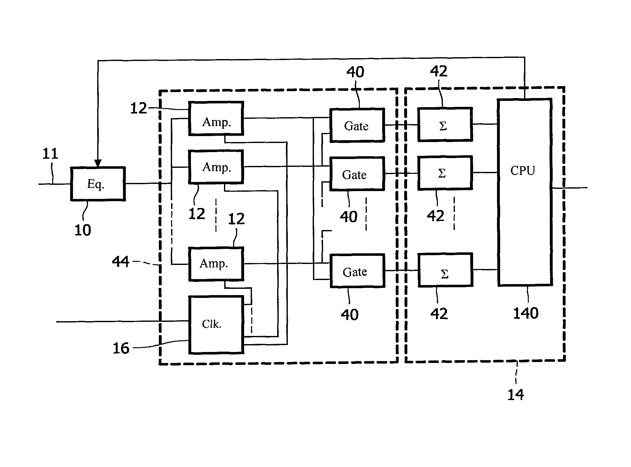
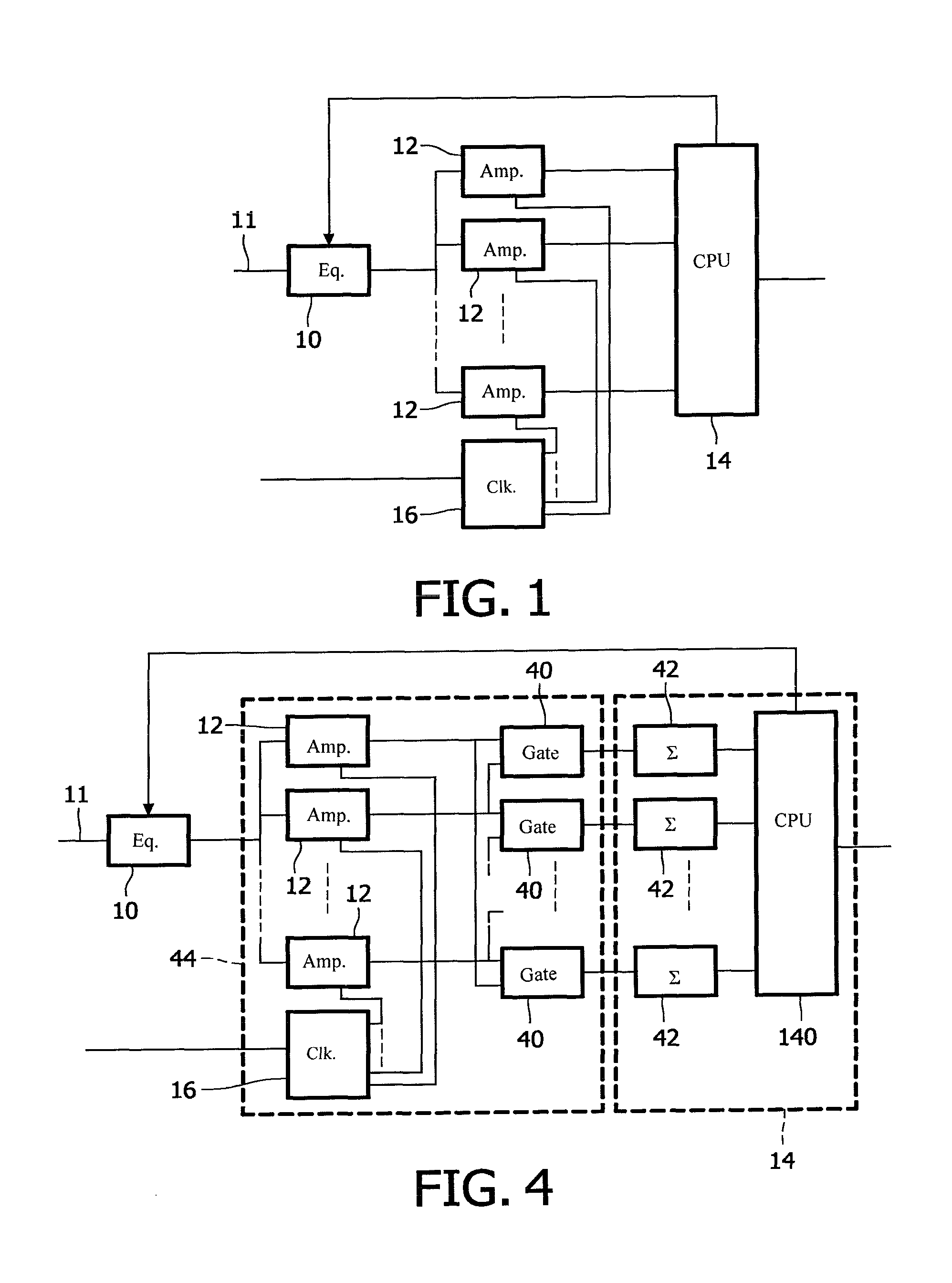
[0033]FIG. 1 shows a simplified block diagram of a receiver circuit for synchronous reception. The circuit comprises an adaptable equalizer 10, a plurality of sampling amplifiers or samplers 12, a digital post-processing circuit 14, a clock recovery circuit 16. A circuit input 11 is coupled to a signal input of equalizer 10, which has an output coupled to each of sampling amplifiers 12. Outputs of sampling amplifier 12 are coupled to digital post-processing circuit 14. Digital post-processing circuit 14 has a first output coupled to a signal output 15 of the circuit and a second output coupled to a setting input of equalizer 10. Clock recovery circuit 16 has outputs coupled to sampling amplifiers 12. An input of clock recovery circuit may be coupled to circuit input 11 or to an external clock source, or to a switch for selecting between a circuit input 11 and an external clock source. Instead of clock recovery circuit 16 a clock multiplying circuit may be used.

[0034]In operation sam...


PUM


Abstract

An adaptive equalizer comprises an adjustable equalizer circuit that allows to enhance the frequency dependence of contents of the transmitted signals which suffer from losses in the connected transmission channel. A blind equalization tuning procedure is proposed that operates without knowledge about the characteristic of transmission channel. Phase positions of transitions in the equalized signal are detected. A digital post-processing circuit evaluates a measure for spread of the detected phase positions of transitions, accumulated over a plurality of the symbol periods. The digital post-processing circuit controls the adjustable equalizer, setting the adjustable equalizer to a setting wherein the detected spread is minimized.

Description

FIELD OF THE INVENTION[0001]The invention relates to data communication circuits. More particularly, the invention relates to auto-adjustment of channel equalization in order to compensate for the frequency dependent distortion of signals transmitted over the communication channel.BACKGROUND ART[0002]The need to equalize signals in high speed communication has been described by J. Liu; et al. in an article titled “Equalization in High-Speed Communication Systems”, published in the IEEE Circuits and Systems Magazine, pages 4-17, 2004.[0003]Wireline communication systems consist conceptually of three different building blocks: a transmitter (TX), a channel (e.g. a cable or optical fiber) and a receiver (RX). Due to non-ideal channel characteristics like limited bandwidth and crosstalk noise, the RX input signals are deteriorated such that the data recovery on the receiver side ends up with unreasonable bit error rates (BER). Increasing system bandwidth requirements in combination with...

Claims


Application Information

Patent Timeline
Patent Type & Authority Patents(United States)
IPC IPC(8): H03H7/30
CPCH04L25/0305H04L25/03885H04L2025/03802H04L2027/0038
Inventor GERFERS, FRIEDELDEN BESTEN, GERRIT WILLEMPETKOV, PAVELKOELLMANN, ANDREASCONDER, JIM E.
Owner NXP BV
Why Eureka
Try Eureka