Structure and method for enhancing interfacial perpendicular anisotropy in CoFe(B)/MgO/CoFe(B) magnetic tunnel junctions
a technology of magnetic tunnel junction and perpendicular anisotropy, which is applied in the direction of magnetic materials for record carriers, magnetic bodies, instruments, etc., can solve the problems of destroying a thin tunnel barrier made of alox, mgo, etc., and affecting the performance of the magnetic tunnel junction, so as to reduce the undesirable soft breakdown component
- Summary
- Abstract
- Description
- Claims
- Application Information
AI Technical Summary
Benefits of technology
Problems solved by technology
Method used
Image
Examples
second embodiment
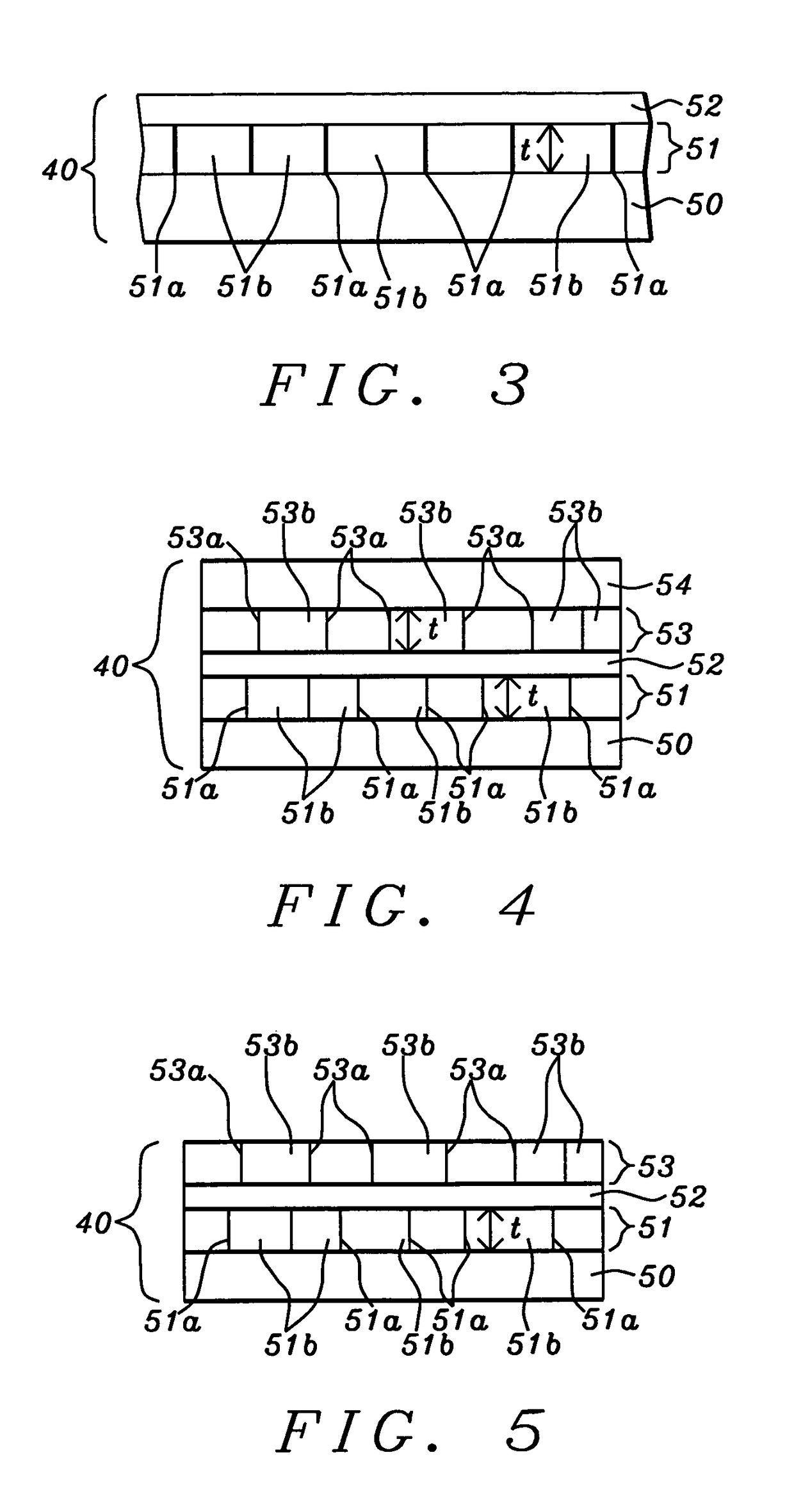
[0054]Referring to FIG. 4, second embodiment of the present invention is depicted that may be referred to as a dual NCC free layer. In particular, the dual NCC free layer 40 configuration in the MTJ stack (FIG. 2) comprises the NCC free layer structure shown in FIG. 3 and an additional second NCC layer 53 and third magnetic (FL3) layer 54 sequentially formed on FL2 layer 52 to give a FL1 / NCC / FL2 / NCC / FL3 structure. In the exemplary embodiment, each of the NCC layers 51, 53 has a thickness from 4 to 6 Angstroms, and preferably 5 Angstroms. The dual NCC configuration has an overall NCC thickness (NCC 51+NCC 53) greater than for a single NCC layer 51 which is typically around 8 Angstroms. Note that NCC layer 53 may be comprised of the same R(M) grains formed in a metal (M) oxide, nitride, or oxynitride insulator matrix previously described with respect to NCC layer 51. Thus, more heat is generated in the granular R(M) columns 51a, 53a for thermally assisting a switch in free layer 40 ma...
third embodiment
[0055]Referring to FIG. 5, the present invention is illustrated and retains all of the features of the dual NCC layer in the previous embodiment except the upper FL3 layer 54 is omitted and the free layer 40 has a FL1 / NCC1 / FL2 / NCC2 configuration. In this case, upper NCC2 layer 53 is the top layer in the free layer stack instead of a FL2 or FL3 layer as in previous embodiments. Preferably, the thickness of FL1 layer 50 is from 14.5 to 15.5 Angstroms and the thickness of FL2 layer 52 is from 6 to 8.5 Angstroms. Both of NCC1 51 and NCC2 53 layers have a thickness from 4 to 6 Angstroms, and preferably 6 Angstroms.
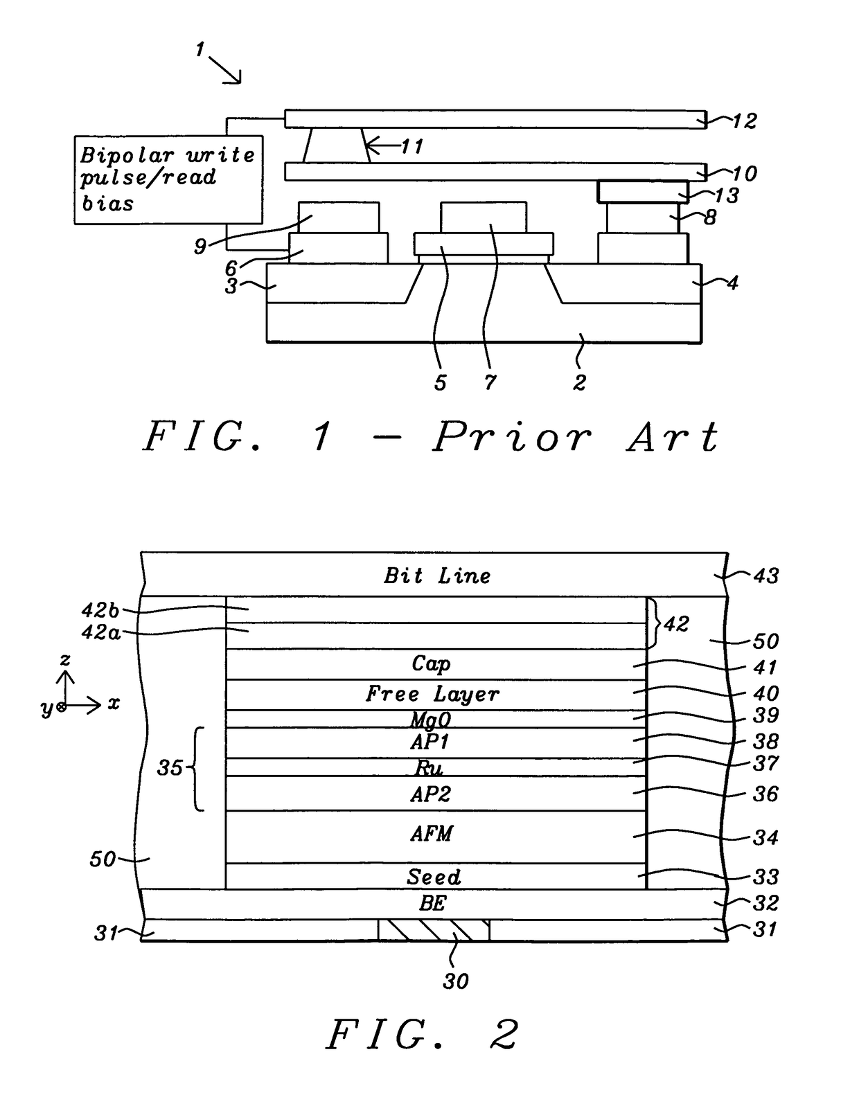
[0056]Returning to FIG. 2, a cap layer 41 is formed on free layer 40 and may be comprised of Ru having a thickness of 10 to 30 Angstroms, and preferably 30 Angstroms. In another embodiment, one or more other metals such as Ta may be employed as a capping layer either as a single layer, an alloy layer, a composite layer comprised of a stack of two or more metal layers, or in com...
PUM
| Property | Measurement | Unit |
|---|---|---|
| thickness | aaaaa | aaaaa |
| thickness | aaaaa | aaaaa |
| thickness | aaaaa | aaaaa |
Abstract
Description
Claims
Application Information
 - R&D
- Intellectual Property
- Life Sciences
- Materials
- Tech Scout
- Unparalleled Data Quality
- Higher Quality Content
- 60% Fewer Hallucinations
Browse by: Latest US Patents, China's latest patents, Technical Efficacy Thesaurus, Application Domain, Technology Topic, Popular Technical Reports.
© 2025 PatSnap. All rights reserved.Legal|Privacy policy|Modern Slavery Act Transparency Statement|Sitemap|About US| Contact US: help@patsnap.com


