
System and methods of amplitude-modulation frequency-modulation (AM-FM) demodulation for image and video processing

a frequency modulation and amplitude modulation technology, applied in the field of image and video processing, can solve the problems that dwt does not measure frequency content directly, and cannot be effectively generalized to images and videos

Active Publication Date: 2013-08-20
STC UNM
View PDF15 Cites 23 Cited by
  • Summary
  • Abstract
  • Description
  • Claims
  • Application Information

AI Technical Summary

Benefits of technology

The present invention provides methods for improving the accuracy of estimates in image processing, video reconfiguration, and medical diagnostics. Specifically, the invention uses digital filters to optimize the estimation of instantaneous amplitude, which helps remove the need for an instantaneous frequency correction step. The condition number of the underlying numerical operations is used to select the method with the highest accuracy for each pixel. The invention also utilizes the AM-FM analysis to extract relevant components and reduce interference by estimating the coefficients of the AM-FM components. Additionally, the invention can detect structures in the retina, such as drusen, and classify them using multi-scale features generated through AM-FM analysis. The invention also provides methods for motion estimation and real-time image quality classification, which reduce computational time by not requiring explicit segmentation of structures.

Problems solved by technology

A disadvantage is that the STFT cannot be effectively generalized to images and videos.
A disadvantage is that DWT does not measure frequency content directly.

Method used


Image

  • System and methods of amplitude-modulation frequency-modulation (AM-FM) demodulation for image and video processing
  • System and methods of amplitude-modulation frequency-modulation (AM-FM) demodulation for image and video processing
  • System and methods of amplitude-modulation frequency-modulation (AM-FM) demodulation for image and video processing

Examples


Embodiment Construction

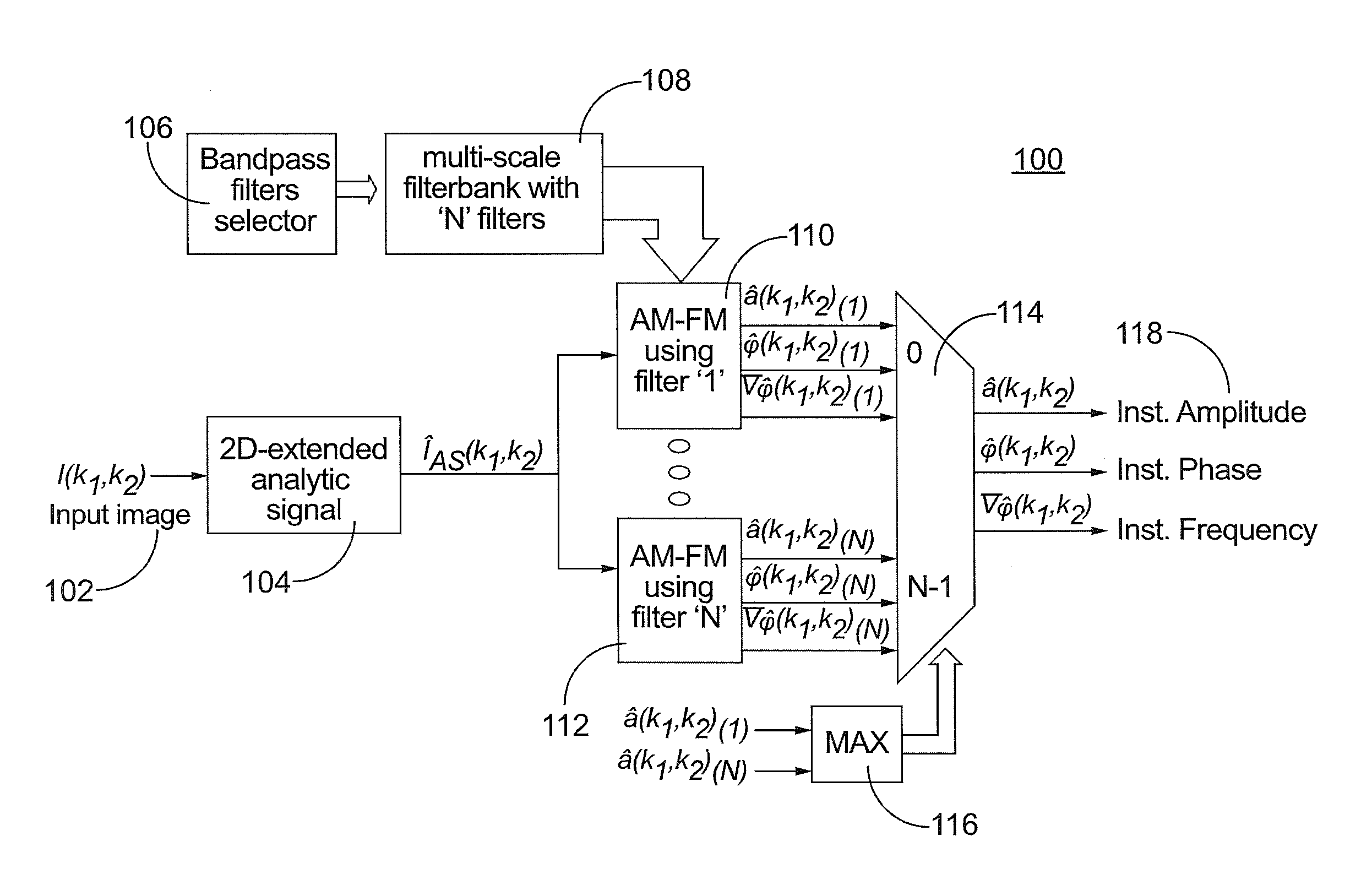
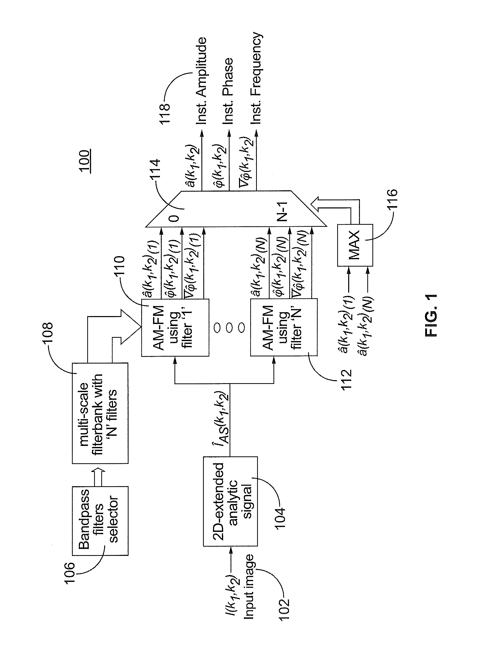
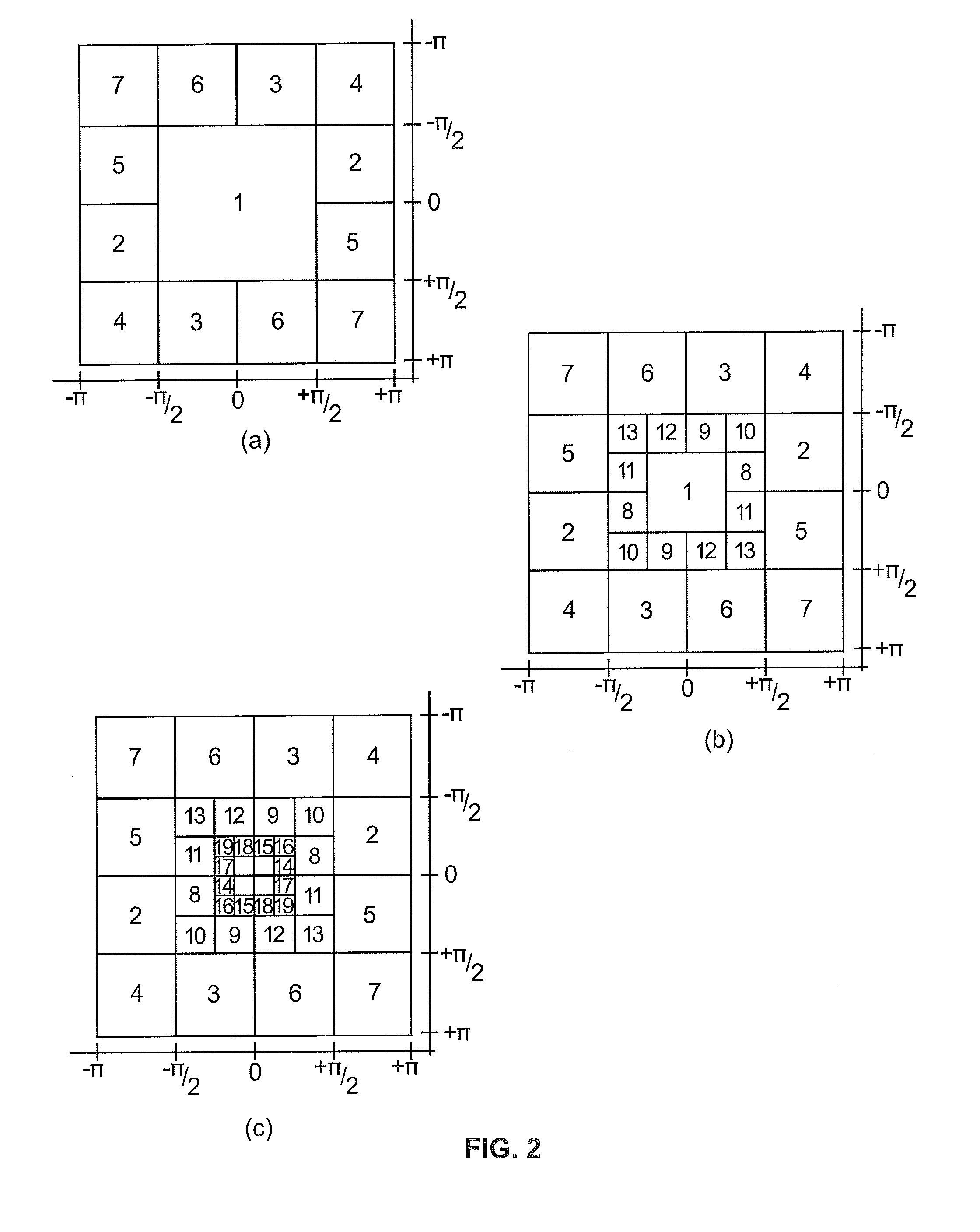
[0064]FIG. 1 illustrates a block diagram of multi-scale AM-FM demodulation 100 according to the present invention, specifically illustrating estimation of a single AM-FM component from a single scale. For purposes of this application, the term “scale” is defined as a collection of bandpass filters. As an example, scales can be categorized into low, medium, and high based on frequency magnitude. As shown in FIG. 1, an input image I(k1,k2) is provided at 102. It is also contemplated that an input video may be provided as described further below. A two-dimensional extended analytic signal IAS(k1,k2) of the input image is computed at 104 by applying the Hilbert transform to form a 2D extension of the 1D analytic signal. For either an input image or input video, a multi-scale filterbank is selected at 106. A multi-scale filterbank is selected by defining the bandpass filters at 108 that correspond to each scale as described in further detail with respect to FIG. 2. The extended analytic ...


PUM


Abstract

Image and video processing using multi-scale amplitude-modulation frequency-modulation (“AM-FM”) demodulation where a multi-scale filterbank with bandpass filters that correspond to each scale are used to calculate estimates for instantaneous amplitude, instantaneous phase, and instantaneous frequency. The image and video are reconstructed using the instantaneous amplitude and instantaneous frequency estimates and variable-spacing local linear phase and multi-scale least square reconstruction techniques. AM-FM demodulation is applicable in imaging modalities such as electron microscopy, spectral and hyperspectral devices, ultrasound, magnetic resonance imaging (“MRI”), positron emission tomography (“PET”), histology, color and monochrome images, molecular imaging, radiographs (“X-rays”), computer tomography (“CT”), and others. Specific applications include fingerprint identification, detection and diagnosis of retinal disease, malignant cancer tumors, cardiac image segmentation, atherosclerosis characterization, brain function, histopathology specimen classification, characterization of anatomical structure such as carotid artery walls and plaques or cardiac motion and as the basis for computer-aided diagnosis to name a few.

Description

PRIORITY STATEMENT[0001]This application claims the benefit of U.S. Provisional Application No. 61 / 098,165 filed Sep. 18, 2008.STATEMENT CONCERNING FEDERALLY SPONSORED RESEARCH[0002]This invention was made with government support under FA9453-06-C-0211 awarded by DARPA and R44EY018280 awarded by the National Institutes of Health. The government has certain rights in the invention.FIELD OF THE INVENTION[0003]This invention relates to image and video processing. More particularly, this invention is directed to a system and methods of Amplitude-Modulation Frequency-Modulation (“AM-FM”) demodulation for processing stationary and non-stationary image and video content.[0004]AM-FM demodulation is useful in a variety of contexts and applications including, for example, characterization and classification of image and video from imaging modalities such as electron microscopy, spectral and hyperspectral devices, ultrasound, magnetic resonance imaging (“MRI”), positron emission tomography (“P...

Claims


Application Information

Patent Timeline
Patent Type & Authority Patents(United States)
IPC IPC(8): G06K9/40G06V10/52
CPCG06K9/527G06V10/52
Inventor MURRAY HERRERA, VICTOR MANUELPATTICHIS, MARIOS STEPHANOUSOLIZ, PETERRIOS, CARLA PAOLA AGURTODAVIS, III, HERBERT T.
Owner STC UNM
Learn More