Cardiac valve annulus restraining device

a technology of annulus and valve, which is applied in the field of medical devices for treating cardiac valve regurgitation, can solve the problems of reducing the function of the valve, leaking backwards, and restricting blood flow

Active Publication Date: 2013-10-08
MEDTRONIC VASCULAR INC
View PDF13 Cites 276 Cited by
  • Summary
  • Abstract
  • Description
  • Claims
  • Application Information

AI Technical Summary

Problems solved by technology

Heart valves, such as the mitral, tricuspid, aortic and pulmonic valves, are sometimes damaged by disease or by aging, resulting in problems with the proper functioning of the valve.
Heart valve problems generally take one of two forms: stenosis, in which a valve does not open completely or the opening is too small, resulting in restricted blood flow; or insufficiency, in which blood leaks backward across a valve when it should be closed.
In common practice, repair or replacement requires open-heart surgery with its attendant risks, expense, and extended recovery time.
Open-heart surgery also requires cardiopulmonary bypass with risk of thrombosis, stroke, and infarction.
Any one or more of the mitral valve structures, i.e., the anterior or posterior leaflets, the chordae, the papillary muscles or the annulus may be compromised by damage from disease or injury, causing the mitral valve insufficiency.
Typically, in cases where there is mitral valve insufficiency, there is some degree of annular dilatation resulting in mitral valve regurgitation.
Thus, without correction, the mitral valve insufficiency may lead to disease progression and / or further enlargement and worsening of the insufficiency.
However, the valve replacement may result in a number of complications including a risk of endocarditis.
Although mitral valve repair and replacement can successfully treat many patients with mitral valve insufficiency, techniques currently in use are attended by significant morbity and mortality.
Those patients undergoing such techniques often have scarring retraction, tears or fusion of valve leaflets, as well as disorders of the subvalvular apparatus.
While the coronary sinus implant provides a less invasive treatment alternative, the placement of the prosthesis within the coronary sinus may be problematic for a number of reasons.
The coronary sinus on a particular individual may not wrap around the heart far enough to allow enough encircling of the mitral valve.
Also, leaving a device in the coronary sinus may result in formation and breaking off of thrombus that may pass into the right atrium, right ventricle and ultimately the lungs causing a pulmonary embolism.
Another disadvantage is that the coronary sinus is typically used for placement of a pacing lead, which may be precluded with the placement of the prosthesis in the coronary sinus.

Method used


Image

  • Cardiac valve annulus restraining device
  • Cardiac valve annulus restraining device
  • Cardiac valve annulus restraining device

Examples


Embodiment Construction

[0021]The invention will now be described by reference to the figures wherein like numbers refer to like structures. The terms “distal” and “proximal” are used herein with reference to the treating clinician during the use of the catheter system; “Distal” indicates an apparatus portion distant from, or a direction away from the clinician and “proximal” indicates an apparatus portion near to, or a direction towards the clinician. Additionally, the term “annuloplasty” is used herein to mean modification / reconstruction of a defective heart valve.

[0022]The current invention discloses devices and methods for treating regurgitation in cardiac valves. While these devices and methods are described below in terms of being used to treat mitral regurgitation, it will be apparent to those skilled in the art that the devices could be used on other cardiac valves also.

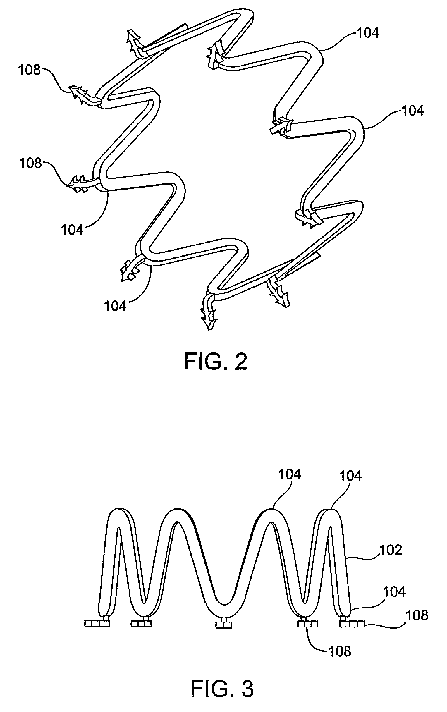
[0023]Referring to the drawings, FIG. 1 shows a schematic cross-sectional view of a heart 1 having tricuspid valve 2 and tricuspid...


PUM


Abstract

A catheter based system for treating mitral valve regurgitation includes a reshaping device having a body and a plurality of movable anchoring barbs attached to the body of the device. The reshaping device can be made from a biocompatible material having suitable shape memory properties. The devices of the current invention can be self expandable, balloon expandable, or a combination self expandable and balloon expandable. One embodiment of the invention includes a method for attaching a reshaping device to the annulus of a mitral valve, moving the body of the device from a fully expanded configuration to a resting configuration, and thereby reshaping the mitral valve annulus.

Description

CROSS-REFERENCE TO RELATED APPLICATION[0001]The present application claims priority to U.S. Provisional Application 60 / 745,557, filed Apr. 25, 2006 and titled “Cardiac Valve Annulus Restraining Device,” the entire contents of which are incorporated herein by reference.TECHNICAL FIELD[0002]This invention relates generally to medical devices for treating cardiac valve regurgitation, particularly to a cardiac valve annulus reshaping system and method of using the same.BACKGROUND OF THE INVENTION[0003]Heart valves, such as the mitral, tricuspid, aortic and pulmonic valves, are sometimes damaged by disease or by aging, resulting in problems with the proper functioning of the valve. Heart valve problems generally take one of two forms: stenosis, in which a valve does not open completely or the opening is too small, resulting in restricted blood flow; or insufficiency, in which blood leaks backward across a valve when it should be closed. Valve replacement may be required in severe cases t...

Claims


Application Information

Patent Timeline
Patent Type & Authority Patents(United States)
IPC IPC(8): A61F2/24
CPCA61F2/2445A61F2/2466A61F2220/0016A61F2210/0014A61F2230/0004A61F2230/0008A61F2/2442A61F2230/0006A61F2230/0019A61F2250/0026A61F2250/0048A61F2250/0069A61F2250/0096
Inventor DOLAN, MARK
Owner MEDTRONIC VASCULAR INC
Why Eureka
Try Eureka