
Method for manufacturing gas diffusion layer for fuel cell

a technology of gas diffusion layer and fuel cell, which is applied in the direction of cell components, final product manufacturing, sustainable manufacturing/processing, etc., to achieve the effects of improving anti-flooding properties, maintaining anti-drying properties, and excellent adaptability against load chang

Active Publication Date: 2013-10-15
NISSAN MOTOR CO LTD
View PDF17 Cites 1 Cited by
  • Summary
  • Abstract
  • Description
  • Claims
  • Application Information

AI Technical Summary

Benefits of technology

[0012]In the method for manufacturing a gas diffusion layer for fuel cells according to the present invention, a gas diffusion layer for fuel cells having excellent adaptability against load change can be produced by determining conditions for coating a coating liquid for forming a conductive fine particle layer on a surface of a substrate for forming a substrate layer to improve anti-flooding properties while maintaining anti-dry-out properties and to ensure a good balance between anti-dry-out properties and anti-flooding properties.
[0013]The gas diffusion layer for fuel cells according to the present invention has excellent adaptability against load change by determining conditions for coating a coating liquid for forming a conductive fine particle layer on a surface of a substrate for forming a substrate layer to improve anti-flooding properties while maintaining anti-dry-out properties and to ensure a good balance between anti-dry-out properties and anti-flooding properties.
[0014]Further, by applying the gas diffusion layer for fuel cells, a fuel cell with excellent adaptability against load change can be provided.

Problems solved by technology

Dry-out or flooding can be a cause of making operation of a fuel cell instable.
The dry-out means a malfunction of a fuel cell wherein electrical resistance of electrolyte membrane increases under dry conditions of a fuel cell to induce instability of the fuel cell.
The flooding means a malfunction of a fuel cell wherein gas passage is blocked due to liquid water generated under moistness conditions of a fuel cell to induce instability of the fuel cell.

Method used


Image

  • Method for manufacturing gas diffusion layer for fuel cell
  • Method for manufacturing gas diffusion layer for fuel cell
  • Method for manufacturing gas diffusion layer for fuel cell

Examples


example 1

Preparation of Gas Diffusion Layer

[0083]Carbon black was used as conductive fine particles, PTFE was used as a water-repellent agent and as a binder for carbon black, and carbon paper was used as a substrate of gas diffusion layer.

(1) Preparation of Coating Liquid (Dispersion of Carbon Black and PTFE)

[0084]A 500 mL beaker was charged with 45 g of acetylene black (HS-100, produced by Denki Kagaku Kogyo K.K.; average particle diameter=48 nm) as a conductive fine particle, 3 g of a surfactant (TRITON X-100, produced by Dow Chemical), and 193 g of pure water. The resultant mixture was stirred at a rotating speed of 80-100 rpm for 1-2 hours using a propeller type stirrer (Three-One Motor BL300, produced by HEIDON) equipped with two stirring wings (soft cross). After confirming that the acetylene black and the surfactant became in a paste-like state and sufficiently dispersed therein, 20 g of PTFE dispersion (Polyflon™ PTFE D-1E, produced by Daikin Industries, Ltd; average particle diamet...

example 2

(1) Preparation of Coating Liquid (Dispersion of Carbon Black and PTFE)

[0087]The same coating liquid as that of Example 1 except that the amount of pure water to be added when the PTFE dispersion was added was changed to 99 g was used as a coating liquid. The viscosities (25° C.) were 3.0 Pa·s (3 rpm) and 0.5 Pa·s (30 rpm).

(2) Coating of Conductive Fine Particle Layer

[0088]The carbon paper used as the substrate was identical to that used in Example 1.

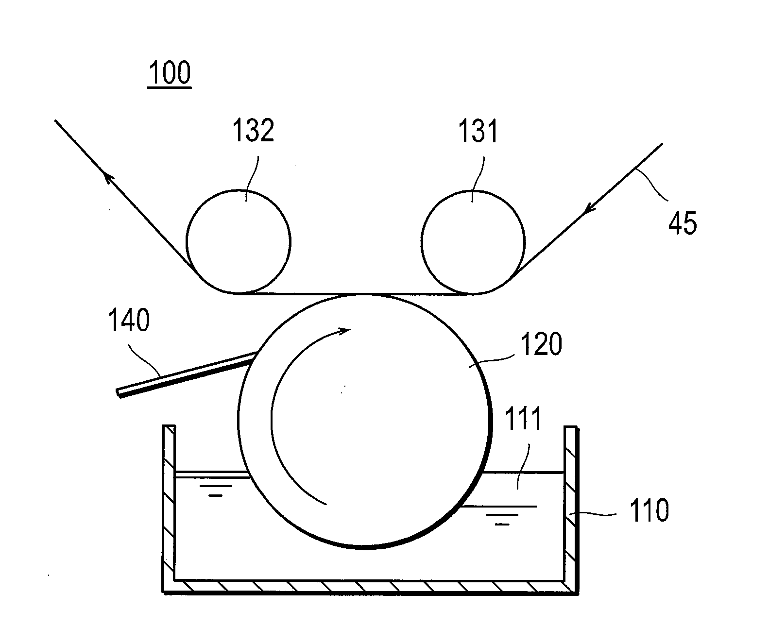
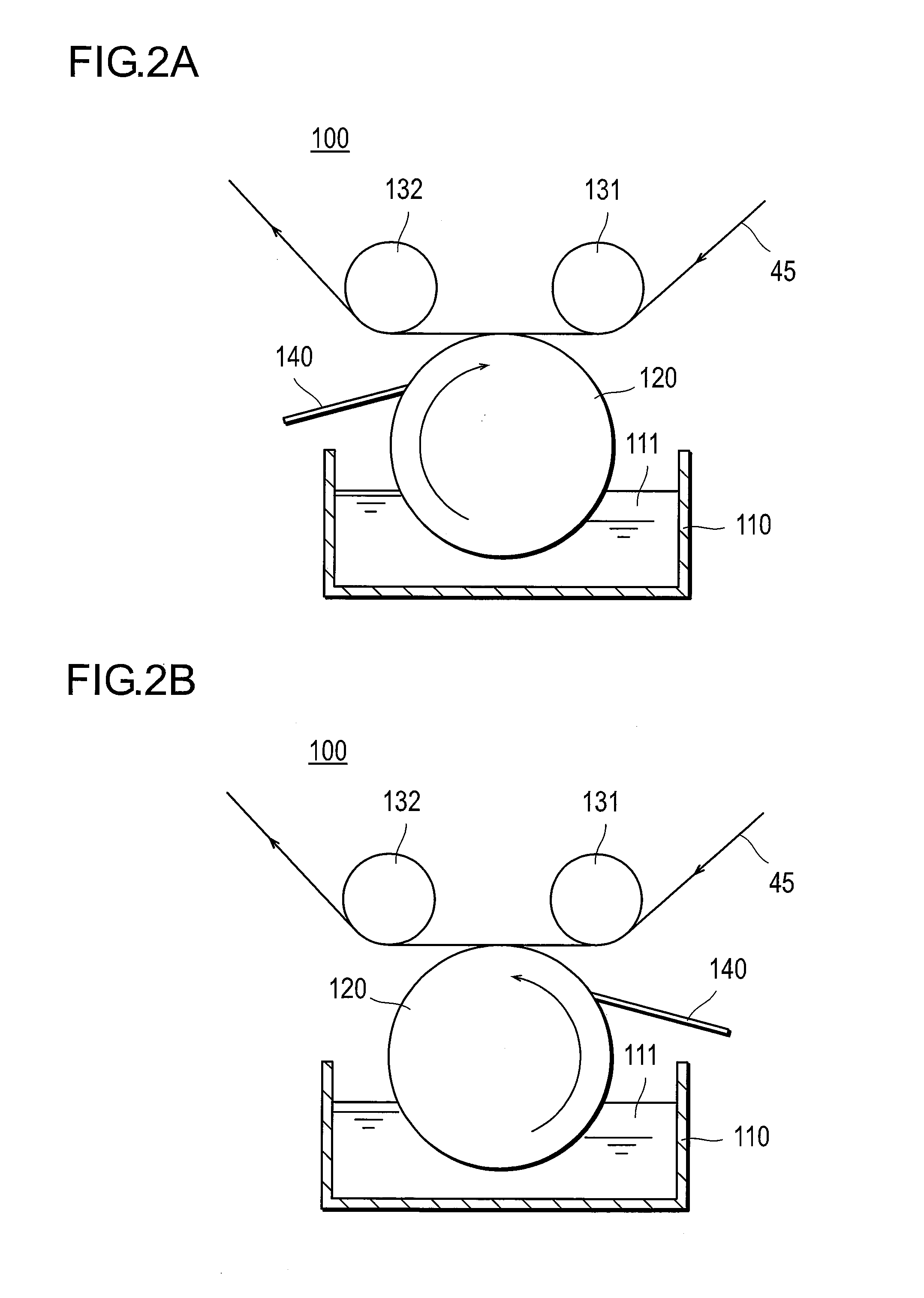
[0089]A gas diffusion layer 2 was obtained under the same conditions including coating device and coating conditions as in Example 1 except that a gravure roll which had a diameter of 150 mm and a width of 280 mm and was formed as grid type 30 (mesh)-260 μm (depth) was used. As the coating liquid of a relatively low concentration (viscosity) was used in the coating, a small amount of the coating liquid seeped out to a surface different from the surface of the substrate to be coated. A coating amount of conductive fine particles was appr...

example 3

(1) Preparation of Coating Liquid (Dispersion of Carbon Black and PTFE)

[0090]The same coating liquid as that of Example 1 was used as a coating liquid.

(2) Coating of Conductive Fine Particle Layer

[0091]The same carbon paper as that of Example 1 was used as a substrate.

[0092]A gas diffusion layer 3 was obtained using the same coating device and the same coating conditions as in Example 1, except that a blade pressure was manually increased and the coating was carried out so as give a coating amount of conductive fine particles of approximately 19 g / m2.


PUM

PropertyMeasurementUnit
outer diameteraaaaaaaaaa
thicknessaaaaaaaaaa
Gurley permeabilityaaaaaaaaaa

Abstract

The invention is to provide a gas diffusion layer for fuel cells having excellent adaptability against load change by attaining a good balance between anti-dry-out properties and anti-flooding properties. The gas diffusion layer for fuel cells containing a substrate layer and an conductive fine particle layer is formed by coating a coating liquid for forming the conductive fine particle layer on at least one surface of a substrate for forming the substrate layer using a gravure roll and by a kiss coating. In coating of the coating liquid, a speed difference is generated between a line speed of transferring the substrate and a circumferential speed of the gravure roll, and apparent viscosity [η(Pa·s)] of the coating liquid as determined by type B viscosimeter satisfies the following relations:1.0<η<200.0 (3 rpm)0.2<η<10.0 (30 rpm).

Description

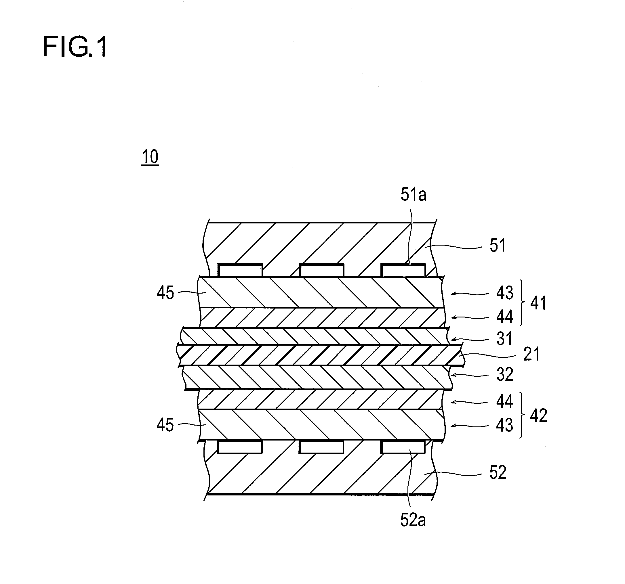
TECHNICAL FIELD[0001]The present invention relates to a method for manufacturing a gas diffusion layer for fuel cells, a gas diffusion layer for fuel cells, and a fuel cell.BACKGROUND[0002]A fuel cell is a power generation device for taking out electrical energy by electrochemically oxidizing fuel such as hydrogen and methanol. The fuel cell has been attracting attentions of the world these days as a clean energy source. The fuel cell can be classified depending on the type of the electrolyte into a phosphoric-acid type, a fused carbonate type, a solid oxide type, a solid polyelectrolyte type, etc. Of these, the polymer electrolyte fuel cell is a type of fuel cell that generates electricity by supply hydrogen on one side and oxygen on the other side of a membrane electrode assembly having electrodes arranged on both sides of an electrolyte membrane. As the polymer electrolyte fuel cell can generate a power density equivalent to that of an internal combustion engine, it has been wide...

Claims


Application Information

Patent Timeline
Patent Type & Authority Patents(United States)
IPC IPC(8): B05D5/12B05D3/12B05D1/28
CPCH01M8/0234H01M4/8821H01M8/0245H01M8/0239H01M8/0243Y02E60/50H01M2008/1095Y02P70/50
Inventor HASEGAWA, TAKUYAWAKI, NORIHISAKUWAHARA, HIROSHI
Owner NISSAN MOTOR CO LTD
Learn More