Method of heat treating a steel bearing component

a technology of bearing components and heat treatment methods, which is applied in the field of metalurgy and to bearing components, can solve the problems of adding production costs, additional steps to be taken to improve surface finish, etc., and achieves the effect of promoting crs and low hardening temperatur

Inactive Publication Date: 2013-10-22
AB SKF
View PDF11 Cites 4 Cited by
  • Summary
  • Abstract
  • Description
  • Claims
  • Application Information

AI Technical Summary

Benefits of technology

[0038]In the third aspect, during the induction heating, the surface of said at least part of the component preferably reaches a temperature of from 900 to 1000° C., more preferably from 920 to 980° C. After quenching, the surface microstructure comprises martensite or at least martensite as the predominant phase. The martensite is preferably present in an amount of at least 50 vol. %, more preferably at least 75 vol. % of the surface microstructure. Such a microstructure is advantageous particularly if step (b) comprises a bainite through-hardening step. In such a case, the steel component comprises a bainite core (bainite as the predominant phase; the bainite is preferably present in an amount of at least 50 vol. %, more preferably at least 75 vol. %) and a martensite surface (martensite as the predominant phase). This results in increased thermal strains between the surface and the core.
[0042]The present invention involves either pre- or post-induction processing in relation to a through-hardening heat-treatment process in order to introduce thermal strains and / or phase transformation strains such that a large compressive residual stress (CRS) is achieved. In particular, the present invention enables a bearing product to be produced with a CRS preferably in the range of −200 to −900 MPa at the near surface, typically being maintained at −300 to −500 MPa at 1 mm depth below the surface. The near surface is typically less than 500 microns below the heat-treated surface. The CRS is superior to conventional bearing components.
[0051]Irrespective of whether one or both of martensite and / or bainite are desired, the steel is preferably austenitised (prior to the quench below / above the martensite start temperature). Austenitising is well known in the art. However, the inventors have found (particularly in relation to the first aspect) that applying through-hardening using a 10-50° C. lower hardening temperature than what would normally be used (e.g. 840 to 890° C.) further promotes the CRS build-up. This is believed to be because the core is under-austenitised in relation to the slightly over-austenitised surface portion. Therefore, the phase transformation differences will be more pronounced. The benefit of having a delayed phase transformation in the surface portion is that it will take place on a fully or partially transformed core, which will restrict the possibility for plastic deformation (phase transformations usually involve a volume increase), and the final surface stress state will therefore become compressive. For these reasons, austenitising is preferably performed at a temperature in the range of from 790 to 890° C., more preferably from 790 to 880° C., still more preferably from 790 to 840° C. The steel is preferably held within this temperature range for from 10 to 70 minutes, more preferably from 20 to 60 minutes.
[0060]For bearings operating at elevated temperatures, higher interference fits are required in order to keep the rings fixed on the shafts. Because higher interference fits result in large hoop stresses, the risk for through cracking increases. Because structural stresses and mounting stresses, such as hoop stresses, are superimposed on microstructure stresses, a through crack can be catastrophic. Large CRS therefore give the possibility to mount bearings with high interference fits with relatively low risk of through cracking. Even if through cracking occurs, the CRS have a crack-closing effect, i.e. a safe-failure mode.

Problems solved by technology

However, this process results in a rough surface finish which can create other problems and therefore additional steps need to be taken to improve the surface finish.
This adds to productions costs.

Method used


Image

  • Method of heat treating a steel bearing component
  • Method of heat treating a steel bearing component
  • Method of heat treating a steel bearing component

Examples


example 1

Pre-processing and Bainite Rehardening

[0070]Test component: Spherical roller bearing (SRB) outer ring with OD 180 mm formed from 100Cr6 steel.

[0071]Pre-processing: Inductive surface heating using ˜10 kHz to reach a surface temperature of ˜1050° C. and a pre-processing depth of ˜2 mm, followed by quenching using a 5% Aquaquench polymer solution.

[0072]Bainite-through hardening: Furnace rehardening using 820° C. and 20 minute soaking time, followed by quenching and transformation in ˜230° C. molten Petrofer AS140 salt for 240 minutes, followed by cooling in still air.

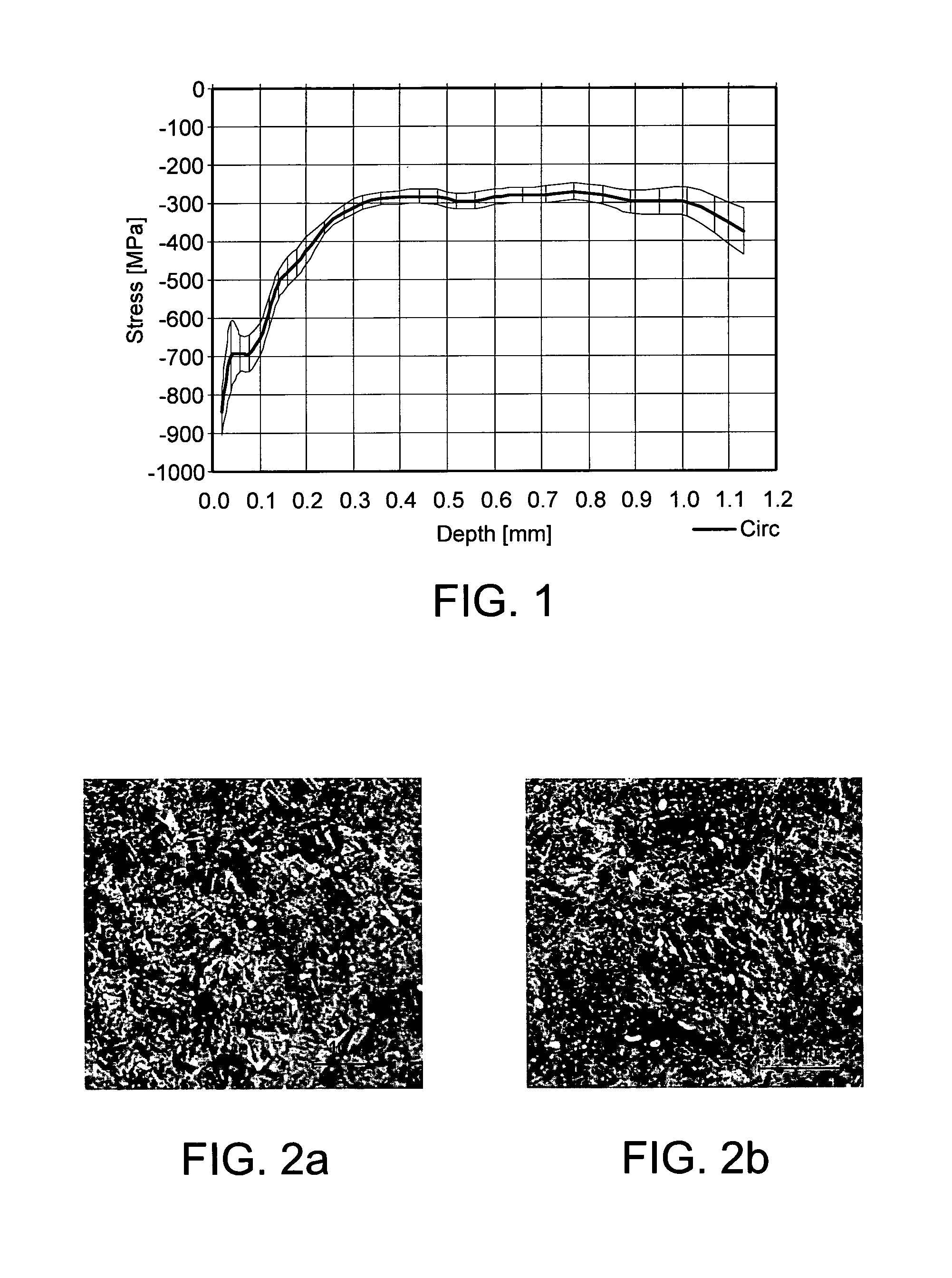
[0073]FIG. 1 is a plot showing the compressive residual stress profile for the component of Example 1. The plot shows a near surface CRS of −300 to −800 MPa. The CRS is maintained at −300 down to at least 1.2 mm.

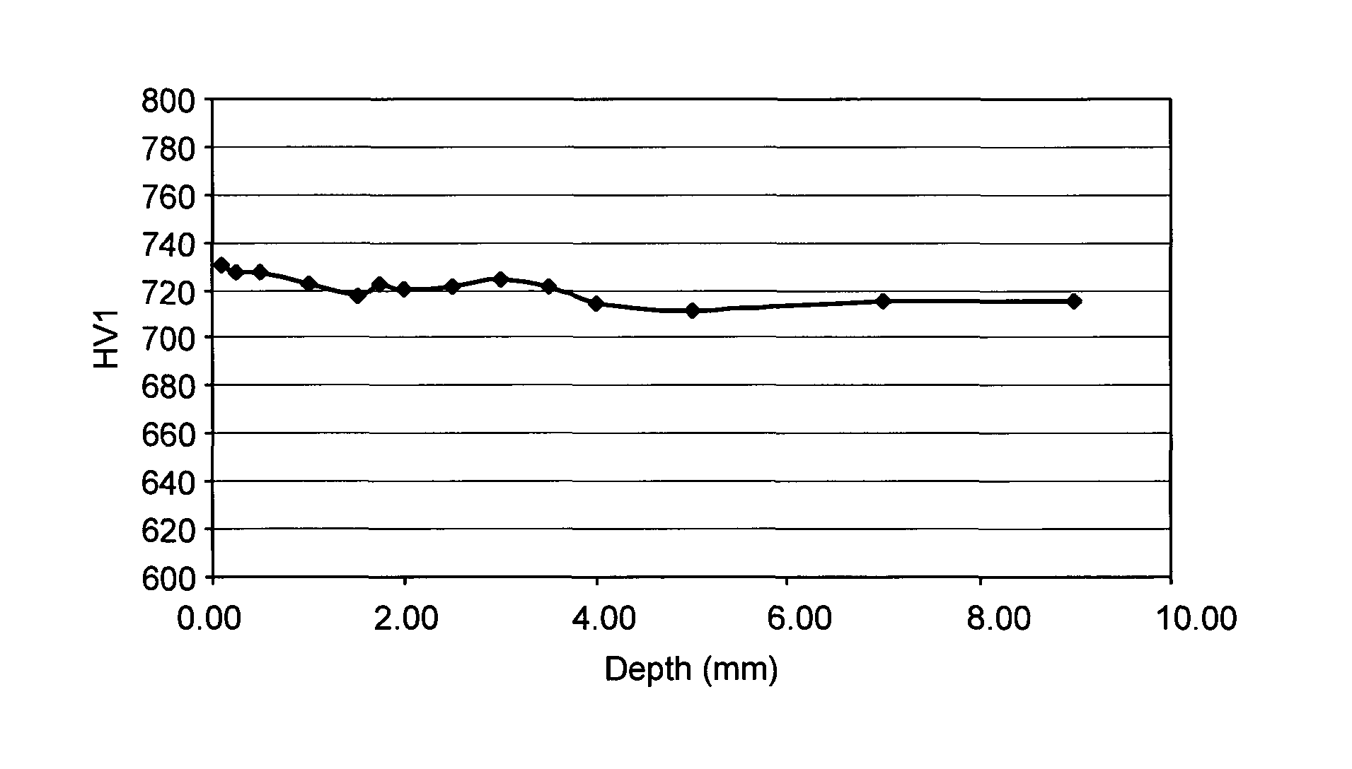
[0074]FIGS. 2a and2b are micrographs showing the surface (a) and core (b) microstructures for the component of Example 1. The micrographs show a bainite microstructure. The surface microstructure is slightly coarse...

example 2

Bainite through Hardening and Post-Processing

[0077]Test component: Cylindrical roller bearing (CRE) inner ring with OD 120 mm formed from 100Cr6 steel

[0078]Bainite through-hardening: Furnace rehardening using 860° C. and 20 min soaking time, followed by quenching and transformation in ˜230° C. molten Petrofer AS140 salt for 240 min, followed by cooling in still air.

[0079]Post-processing: Inductive surface heating using ˜8 kHz to reach a surface temperature of ˜940° C. and a case depth of ˜1.8 mm, followed by quenching using a 5% Aquatensid polymer quench solution and tempering at 160° C. for 60 min

[0080]FIG. 5 is a plot showing the compressive residual stress profile for the component of Example 2 after the heat-treatment and compared to standard martensite and standard bainite.

[0081]FIGS. 6a, 6b and 6c are micrographs showing the surface (a), transitional zone (b), and core (c) microstructures for the component of Example 2 after the bainite through-hardening and induction heating ...

example 3

Martensite through Hardening and Post-Processing Under Interference Fit

[0083]Test component: Deep groove ball bearing (DGBB) inner ring with OD 62 mm formed from 100Cr6 steel

[0084]Martensite through Hardening: Furnace rehardening using 860° C. and 20 min soaking time, followed by oil quenching in 60° C. oil and tempering at 160° C. for 60 min

[0085]Post-processing: Mounting on over-sized shaft resulting in hoop-stress. Inductive surface heating using ˜90 kHz to reach a surface temperature of ˜940° C. and a case depth of ˜1.8 mm, followed by quenching using a 5% Aquatensid polymer quench solution and tempering at 160° C. for 60 min. Removal of shaft.

[0086]FIG. 8 is a plot showing the CRS profile for the component of Example 3 after the martensite through-hardening and induction heating steps with different levels of hoop stress.


PUM

PropertyMeasurementUnit
depthaaaaaaaaaa
depthaaaaaaaaaa
temperatureaaaaaaaaaa

Abstract

A bearing component formed from a bearing steel, wherein the component has an outer surface and comprises through-hardened bainite and / or martensite and has a substantially homogeneous chemical composition, at least a part of the bearing component having a compressive residual stress profile comprising −25 to −1000 MPa at the near surface, wherein the near surface is defined as a region 500 microns or less below the outer surface.

Description

BACKGROUND OF THE INVENTION[0001]The present invention relates generally to the field of metallurgy and to a bearing component such as a rolling element or ring formed from a bearing steel. A heat- treatment induces a compressive residual stress (CRS) in a surface region of the bearing steel with the corollary of an improvement in mechanical properties, for example rolling contact fatigue performance.[0002]Bearings are devices that permit constrained relative motion between two parts. Rolling element bearings comprise inner and outer raceways and a plurality of rolling elements (ball bearings or roller bearings). For long-term reliability and performance it is important that the various elements have a high resistance to rolling fatigue, wear and creep.[0003]Conventional techniques for manufacturing metal components involve hot-rolling or hot-forging to form a bar, rod, tube or ring, followed by a soft forming process to obtain the desired component. Surface hardening processes are ...

Claims


Application Information

Patent Timeline
Patent Type & Authority Patents(United States)
IPC IPC(8): C21D9/40C21D1/10
CPCC21D1/10C21D1/20C21D9/40C21D1/25C21D2211/008C21D2211/002F16C33/62C21D1/22Y02P10/25
Inventor STRANDELL, INGEMARNEUMAN, PETERSUNDQVIST, BERNDT MIKAELLANE, STEVEN
Owner AB SKF
Why Eureka
Try Eureka