Substrate heat treatment apparatus

a heat treatment apparatus and substrate technology, applied in the direction of lighting and heating apparatus, charge supports, furniture, etc., can solve the problems of increasing the curvature of the substrate, serious variations in the heat history over the substrate surface, and difficulty in meeting the requirements of temperature uniformity, so as to prevent the buckling of the support device, suppress the heat history over the substrate surface, and effectively suck

Active Publication Date: 2013-12-17
DAINIPPON SCREEN MTG CO LTD
View PDF15 Cites 411 Cited by
  • Summary
  • Abstract
  • Description
  • Claims
  • Application Information

AI Technical Summary

Benefits of technology

[0010]This invention has been made having regard to the state of the art noted above, and its object is to provide a substrate heat treatment apparatus for heat-treating a substrate effectively while suppressing variations in heat history over a substrate surface between contact parts in contact with support devices and non-contact parts out of contact with the support devices.

Problems solved by technology

However, with enlarged substrate sizes, increased curvatures of substrates take place in the semiconductor manufacturing process.
It is difficult to satisfy the requirements for temperature uniformity in a proximity heating mode that heats each substrate only by placing the substrate as separated by a minute space from a heat-treating plate.
The rate of temperature increase differs greatly between the contact parts and non-contact parts, causing serious variations in heat history over the substrate surface.
As a result, a pattern of uniform line width cannot be formed on the substrate.
This results in the inconvenience of the rate of temperature increase differing greatly between the contact parts and non-contact parts, causing serious variations in heat history over the substrate surface.

Method used


Image

  • Substrate heat treatment apparatus
  • Substrate heat treatment apparatus
  • Substrate heat treatment apparatus

Examples


embodiment 1

[0044

[0045]Embodiment 1 of this invention will be described hereinafter with reference to the drawings.

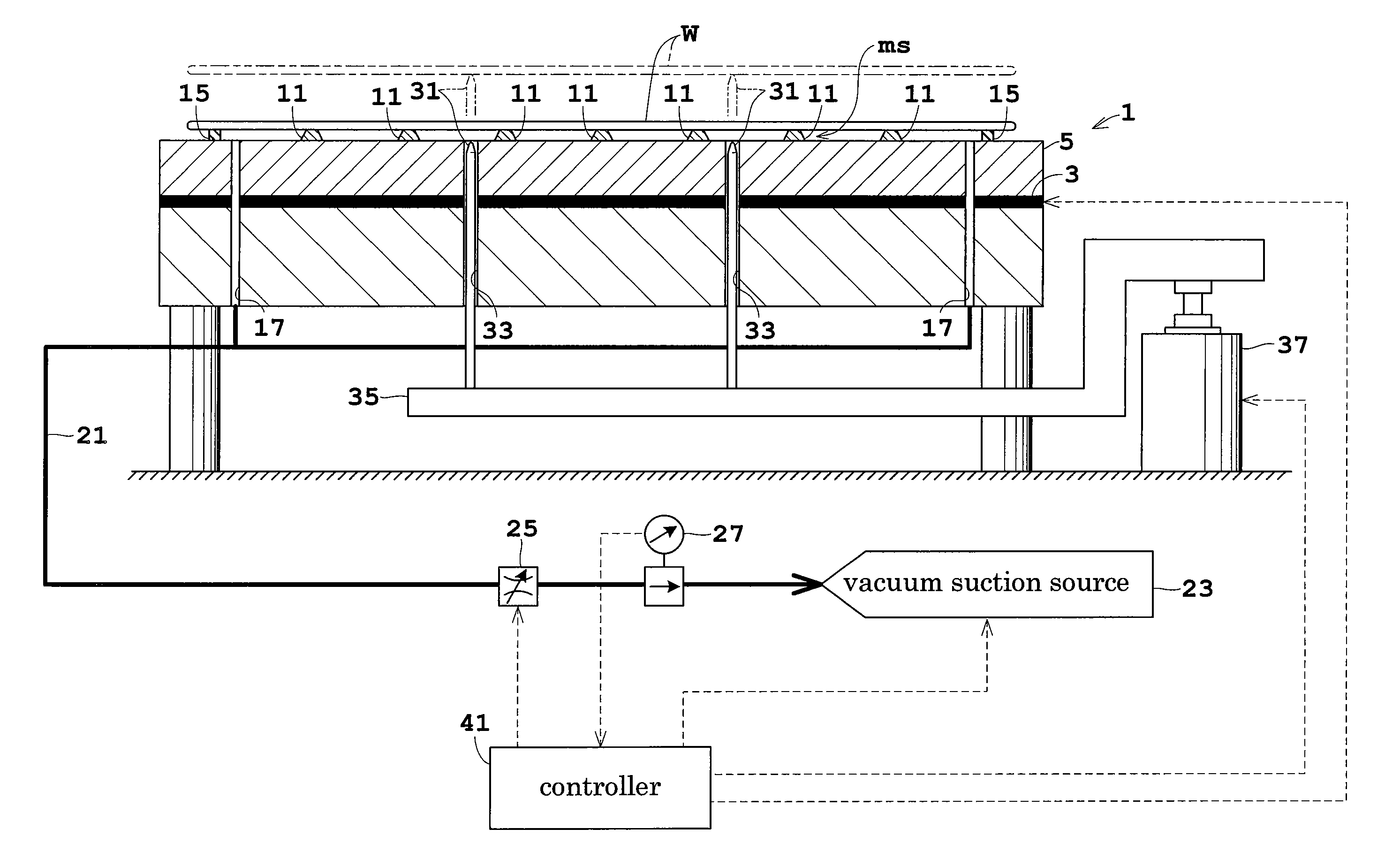
[0046]FIG. 1 is a view in vertical section showing an outline of a substrate heat treatment apparatus in Embodiment 1.

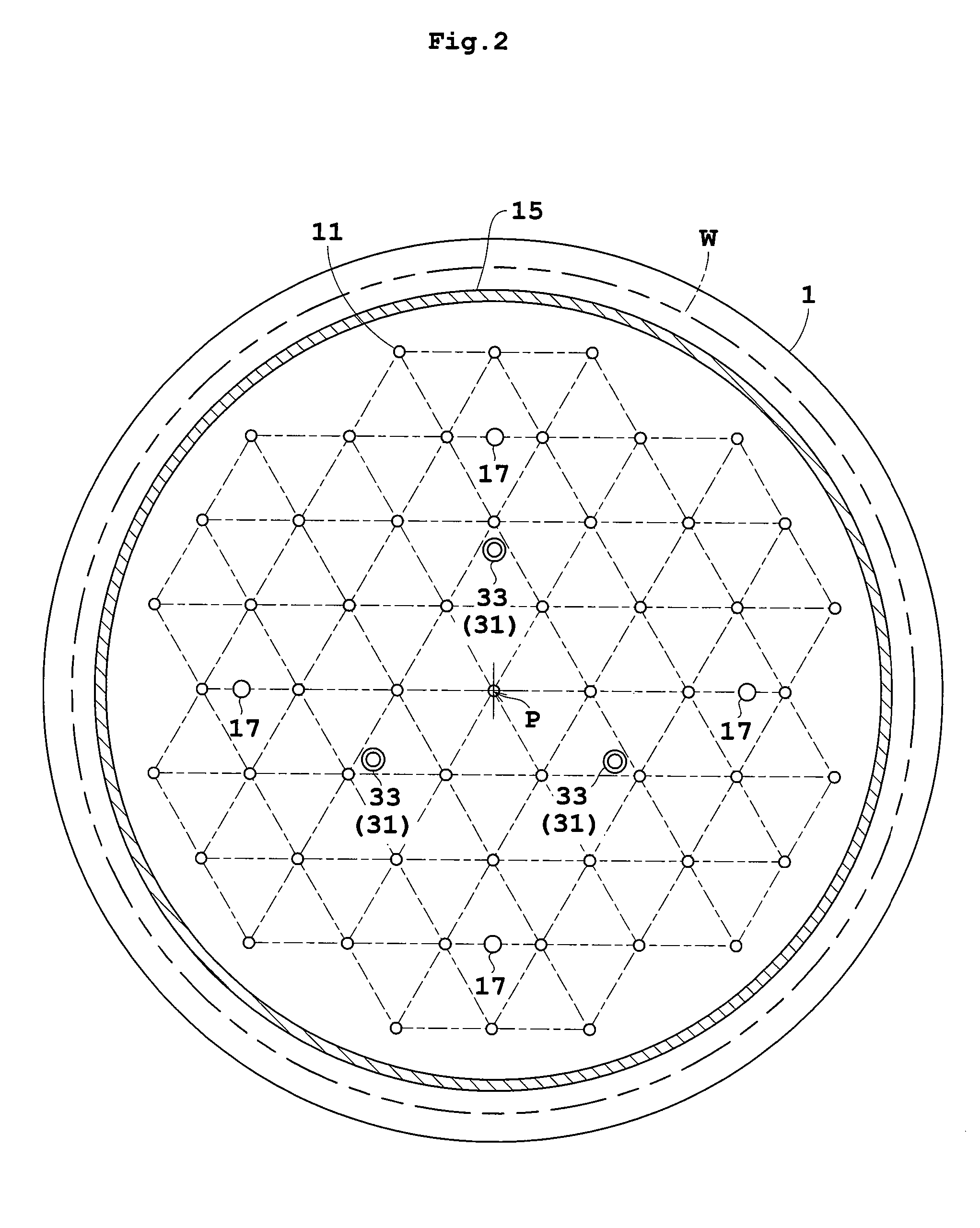
[0047]FIG. 2 is a plan view of a heat-treating plate.

[0048]A heat-treating plate 1 for supporting a substrate or wafer W under treatment is circular and has a slightly larger diameter than the wafer W in plan view. The upper surface of the plate 1 is flat. The heat-treating plate 1 is formed of a metal such as copper or aluminum having high thermal conductivity, for example. The heat-treating plate 1 has a heating element 3 such as a mica heater mounted therein. A heat transfer portion 5 between the heating element 3 and the upper surface of heat-treating plate 1 has a plurality of heat pipes, not shown, embedded therein. Cooling grooves, not shown, are formed between the heat pipes for circulating a cooling fluid.

[0049]The heat-treating plate 1 has a plurality of (...

embodiment 2

[0069

[0070]Embodiment 2 of this invention will be described hereinafter with reference to the drawings. Like reference numerals are used to identify like parts which are the same as in Embodiment 1 and will not particularly be described. FIG. 6A is a plan view of a heat-treating plate. FIG. 6B is a view in vertical section of the heat-treating plate.

[0071]Embodiment 2 is different from Embodiment 1 in support elements 12. The heat-treating plate 1 has a plurality of (e.g. four) support elements 12 arranged in concentric circles. More particularly, the support elements 12 are ring-shaped, different in diameter, and arranged concentrically about the center point P on the upper surface of heat-treating plate 1. Each support element 12 has a sectional shape tapering from a lower portion to an upper portion that contacts a wafer W. Grooves 18 are formed in varied positions of each support element 12 for allowing communication between regions inside and outside each support element 12. Th...

embodiment 3

[0075

[0076]Embodiment 3 of this invention will be described hereinafter with reference to FIG. 7. Like reference numerals are used to identify like parts which are the same as in Embodiment 1 and will not particularly be described. FIG. 7 is a sectional view of a heat-treating plate.

[0077]Embodiment 3 is different from Embodiment 1 in having a support and seal member 13 instead of the support elements 11 and sealer 15. The support and seal member 13 is a sheet-like object having projections 13b formed thereon for contacting a wafer W. More particularly, the support and seal member 13 includes a sheet-like base 13a covering the entire surface of heat-treating plate 1 and having, formed thereon, a plurality of projections 13b, and a ring-shaped ridge 13c having an inside diameter slightly smaller than the outside diameter of the wafer W. The support and seal member 13 has openings formed in positions opposed to the exhaust bores 17 and perforations 33.

[0078]Each projection 13b is pill...


PUM

PropertyMeasurementUnit
diameteraaaaaaaaaa
diameteraaaaaaaaaa
thicknessaaaaaaaaaa

Abstract

A substrate heat treatment apparatus includes a heat-treating plate having a flat upper surface, support devices formed of a heat-resistant resin for contacting and supporting a substrate, a seal device disposed annularly for rendering gastight a space formed between the substrate and heat-treating plate, and exhaust bores for exhausting gas from the space. The support devices are formed of resin, and the upper surface of the heat-treating plate is made flat, whereby a reduced difference in the rate of heat transfer occurs between contact parts and non-contact parts on the surface of the substrate. Consequently, the substrate is heat-treated effectively while suppressing variations in heat history over the surface of the substrate.

Description

BACKGROUND OF THE INVENTION[0001](1) Field of the Invention[0002]This invention relates to a substrate heat treatment apparatus for heat-treating substrates such as semiconductor wafers, glass substrates for liquid crystal displays, glass substrates for photomasks and substrates for optical disks (hereinafter simply called “substrates”). More particularly, the invention relates to a technique for heat-treating a substrate as sucked in a position slightly spaced from a heat-treating plate.[0003](2) Description of the Related Art[0004]With an increasingly fine line width of patterns formed on substrates today, the requirements for line width uniformity have become stringent, which has led to a strong demand for temperature uniformity in baking treatment in photolithography, especially in baking treatment after exposure (PEB: Post Exposure Bake). However, with enlarged substrate sizes, increased curvatures of substrates take place in the semiconductor manufacturing process. It is diffi...

Claims


Application Information

Patent Timeline
Patent Type & Authority Patents(United States)
IPC IPC(8): B29C65/02
CPCF27D5/0037H01L21/6875H01L21/68757
Inventor GOTO, SHIGEHIROMATSUCHIKA, KEIJIMORITA, AKIHIKO
Owner DAINIPPON SCREEN MTG CO LTD
Why Eureka
Try Eureka