Friction stir fabrication
a technology of friction stir and fabrication method, which is applied in the direction of manufacturing tools, soldering devices, auxillary welding devices, etc., can solve the problems that conventional techniques are not suitable for processing many types of substrates and coating materials, and achieve the effects of reducing oxide content, superior bond strength, and density
- Summary
- Abstract
- Description
- Claims
- Application Information
AI Technical Summary
Benefits of technology
Problems solved by technology
Method used
Image
Examples
example 1
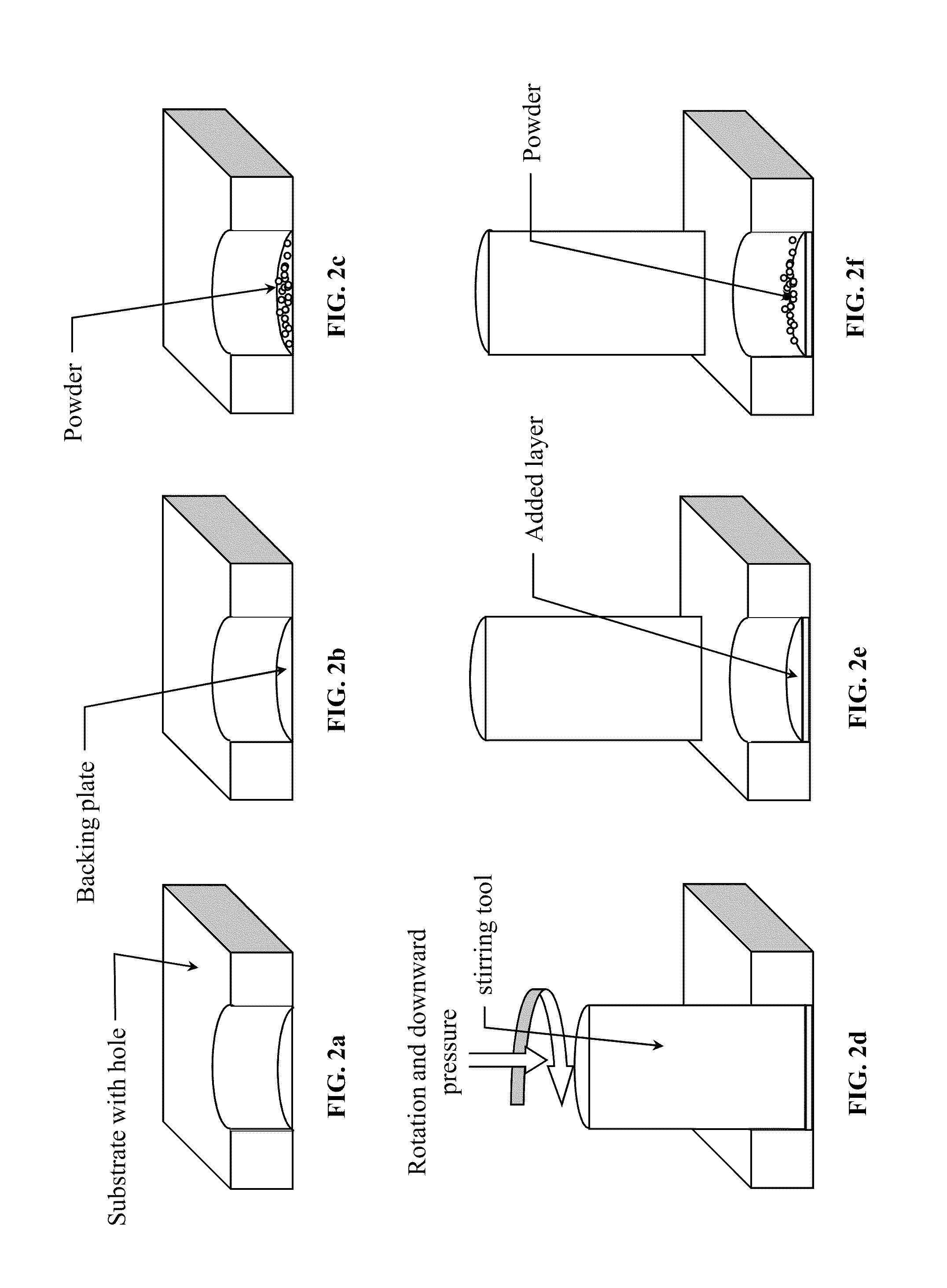
[0048]5083 Al plate was coated with nanocrystalline aluminum deposit. Because the nanocrystalline Al was a limited supply and in powder form, the coating deposit was made using the “hole-filling” method and the interface at the bottom of the hole was the interface of interest. FIG. 4 shows representative stress-strain curves for bulk 5083 Al, and the 5083 Al substrate with nanocrystalline Al coating. The micrographs of FIGS. 5 and 6 show the interfacial region between the substrate and the deposit as polished and etched, respectively. The microstructure in the nanocrystalline region is very fine while the 5083 is characterized by large precipitates and large high aspect ratio grains.
[0049]Consolidated deposits of nanocrystalline Al powder are preferably homogenous and fully dense. All of the 5083 Al-nanocrystalline Al tensile specimens tested failed at or near the interface at approximately 75-95% of the bulk 5083 ultimate tensile strength, indicating that metallurgical bonding occu...
example 2
[0051]An aluminum substrate was coated with an Al—SiC metal matrix composite. SiC-powder-filled 6063 Al tubes were used as the deposition material for samples with an Al—SiC MMC coating. The matrix for the MMC coating may be commercially pure (CP) Al, however, CP Al tubes of the desired diameter may not be readily available. Therefore, 6063 T5 Al tubes may be substituted for CP Al tubes for this demonstration. 6063 Al was selected because it contains silicon, which limits the dissolution of silicon from the silicon carbide reinforcement. Such dissolution would lead to the formation of Al4C3, a detrimental brittle phase. The average particle size (APS) of the SiC powder used was 1 mm and the volume fraction of SiC in the composites was approximately 10 vol. %.
example 3
[0052]A 5083 Al plate was coated with an Al—SiC metal matrix composite. To test the bond strength between 5083 Al and 6063 Al—SiC (10 v %), a ½-inch thick MMC coating was deposited on a 5083 Al substrate using FSF with SiC filled 6063 Al T5 tubes as the feed rod. FIG. 7 shows a stress-strain curve for the 5083 Al substrate and the interface between the substrate and the Al—SiC metal matrix composite coating. A cross-section of the polished MMC coating and substrate are shown on the right side of FIG. 8. Significant improvements in both the coating and interfacial microstructure have been made. The improvements primarily result from the use of a threaded-tapered stirring tool for post-deposition friction stir processing. A friction stir processing pass was made (the stirring tool translated normal to the cross-section shown in the micrograph) after each incremental increase in the coating thickness of approximately ⅛-inch. As is evident from the micrograph, the friction stir processe...
PUM
| Property | Measurement | Unit |
|---|---|---|
| crystal grain size | aaaaa | aaaaa |
| crystal grain size | aaaaa | aaaaa |
| temperature | aaaaa | aaaaa |
Abstract
Description
Claims
Application Information
 - R&D
- Intellectual Property
- Life Sciences
- Materials
- Tech Scout
- Unparalleled Data Quality
- Higher Quality Content
- 60% Fewer Hallucinations
Browse by: Latest US Patents, China's latest patents, Technical Efficacy Thesaurus, Application Domain, Technology Topic, Popular Technical Reports.
© 2025 PatSnap. All rights reserved.Legal|Privacy policy|Modern Slavery Act Transparency Statement|Sitemap|About US| Contact US: help@patsnap.com


