
Exhaust system for a lean-burn IC engine comprising a PGM component and a SCR catalyst

a technology of exhaust system and lean-burn ic engine, which is applied in the direction of machines/engines, metal/metal-oxide/metal-hydroxide catalysts, etc., can solve the problems of unintended engine upset, uncontrolled or poorly controlled regeneration events, and uncontrollable or poorly controlled conditions, so as to reduce or prevent poisoning

Active Publication Date: 2014-03-11
JOHNSON MATTHEY PLC
View PDF77 Cites 20 Cited by
  • Summary
  • Abstract
  • Description
  • Claims
  • Application Information

AI Technical Summary

Benefits of technology

The invention relates to a method and system to prevent the poisoning of a selective catalytic reduction (SCR) catalyst in an exhaust system of a lean-burn internal combustion engine caused by the volatilization of nitrogen oxide (NOx) from a platinum group metal (PGM) catalyst upstream of the SCR catalyst. The invention utilizes a substrate monolith that comprises a material for trapping volatilized PGM to prevent its migration to the SCR catalyst and resulting in reduced or prevented poisoning. The technical benefits include reduced NOx emissions, improved SCR performance, and increased durability of the exhaust system components.

Problems solved by technology

Such conditions may also be experienced with unintended occasional engine upset modes or uncontrolled or poorly controlled regeneration events.
However, some diesel engines, particularly heavy duty diesel engines operating at high load, may even expose catalysts to significant temperatures, e.g. >600° C. under normal operating conditions.
Although it is possible to coat a surface of a filter monolith, e.g. an inlet channel surface of a wall-flow filter, with more than one layer of catalyst composition, an issue with coating filtering monoliths is to avoid unnecessarily increasing back-pressure, when in use, by overloading the filter monolith with catalyst washcoat, thereby restricting the passage of gas therethrough.
Incomplete hydrolysis of urea can lead to increased PM emissions on tests for meeting the relevant emission test cycle because partially hydrolysed urea solids or droplets will be trapped by the filter paper used in the legislative test for PM and counted as PM mass.
Furthermore, the release of certain products of incomplete urea hydrolysis, such as cyanuric acid, is environmentally undesirable.
This can have a highly detrimental effect on the performance of the SCR catalyst, since the presence of Pt leads to a high activity for competing, non-selective ammonia oxidation such as in reaction (9) (which shows the complete oxidation of NH3), thereby producing secondary emissions and / or unproductively consuming NH3.

Method used


Image

  • Exhaust system for a lean-burn IC engine comprising a PGM component and a SCR catalyst
  • Exhaust system for a lean-burn IC engine comprising a PGM component and a SCR catalyst
  • Exhaust system for a lean-burn IC engine comprising a PGM component and a SCR catalyst

Examples


example 1

Preparation of Substrate Monolith Coated with 5 wt % Fe / Beta Zeolite

[0081]Commercially available Beta zeolite was added to an aqueous solution of Fe(NO3)3 with stiffing. After mixing, binders and rheology modifiers were added to form a washcoat composition.

[0082]A 400 cells per square inch cordierite flow-through substrate monolith was coated with an aqueous slurry of the 5 wt % Fe / Beta zeolite sample using the method disclosed in Applicant / Assignee's WO 99 / 47260, i.e. comprising the steps of (a) locating a containment means on top of a support, (b) dosing a pre-determined quantity of a liquid component into said containment means, either in the order (a) then (b) or (b) then (a), and (c) by applying pressure or vacuum, drawing said liquid component into at least a portion of the support, and retaining substantially all of said quantity within the support. This coated product (coated from one end only) is dried and then calcined and this process is repeated from the other end so tha...

example 3a and 3b

Preparation of Alumina Guard Beds

[0085]A 400 cells per square inch cordierite flow-through substrate monolith was coated with an aqueous slurry comprising particulate alumina using the method disclosed in Applicant / Assignee's WO 99 / 47260. The solids content was selected to prepare two different washcoat loadings: a first (designated Example 3A) of 1.0 g / in3; and a second (3B) of 0.4 g / in3. The resulting parts were dried, then calcined.

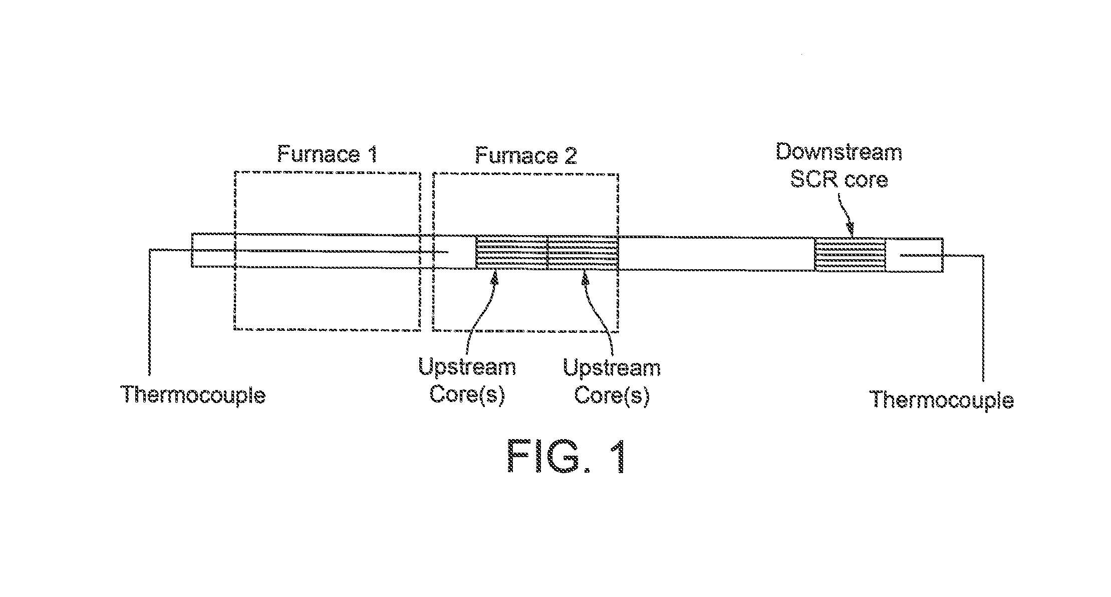
[0086]A core of 1 inch (2.54 cm) diameter×3 inches (7.62 cm) long was cut from the finished article.

example 4a and 4b

Preparation of Ceria:Zirconia Mixed Oxide Guard Beds

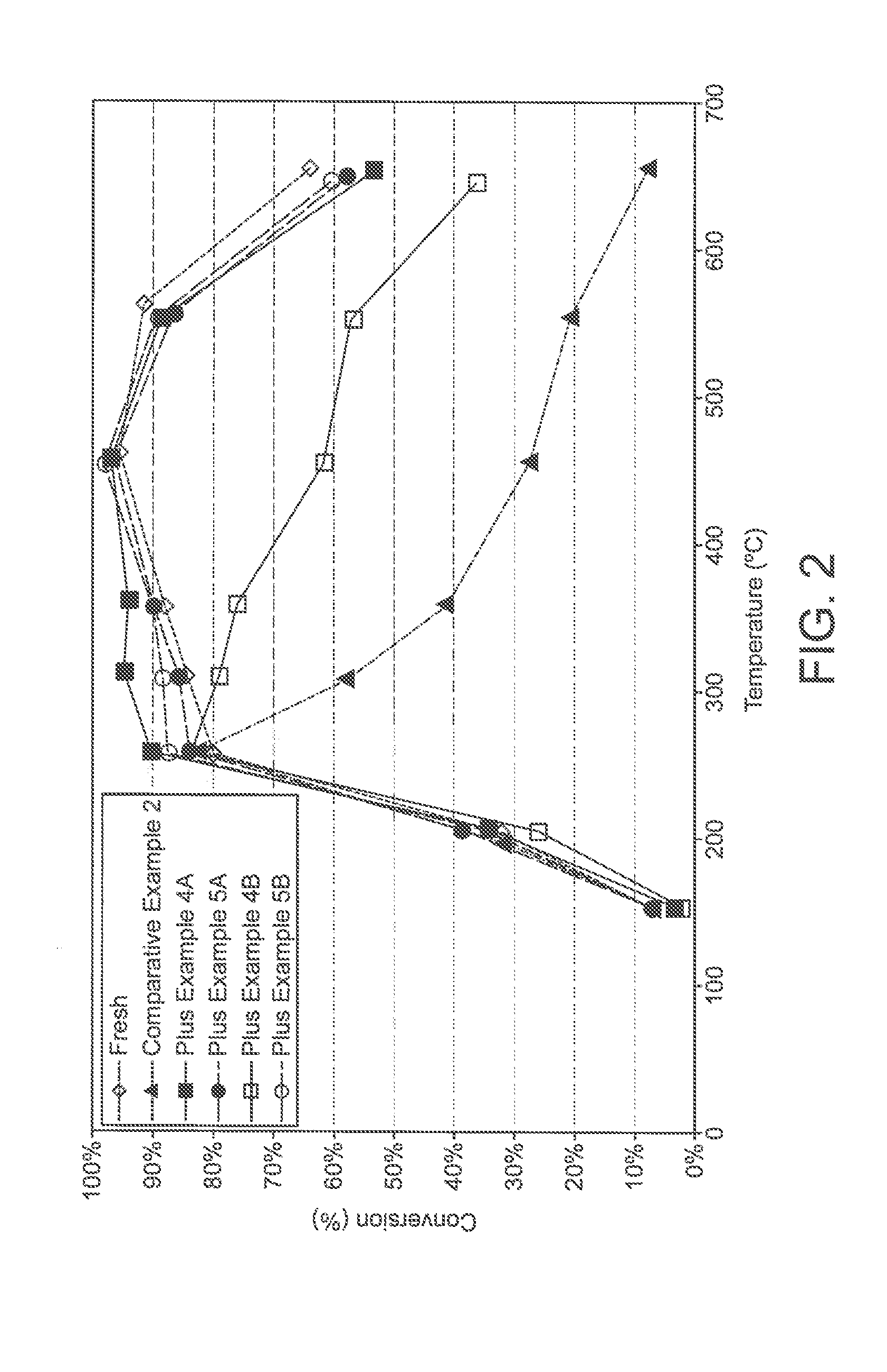
[0087]A 400 cells per square inch cordierite flow-through substrate monolith was coated with an aqueous slurry comprising a particulate ceria:zirconia mixed oxide using the method disclosed in Applicant / Assignee's WO 99 / 47260. Two different ceria:zirconia mixed oxide materials were used. A first (designated Example 4A) had a ceria:zirconia weight ratio of 9:1; whereas a second (4B) had ceria:zirconia weight ratio of 1:9. Both ceria:zirconia mixed oxides were coated on the flow-through substrate monolith at a washcoat loading of 1.0 g / in3. The resulting parts were dried, then calcined.

[0088]A core of 1 inch (2.54 cm) diameter×3 inches (7.62 cm) long was cut from the finished article.


PUM

PropertyMeasurementUnit
temperaturesaaaaaaaaaa
temperatureaaaaaaaaaa
temperaturesaaaaaaaaaa

Abstract

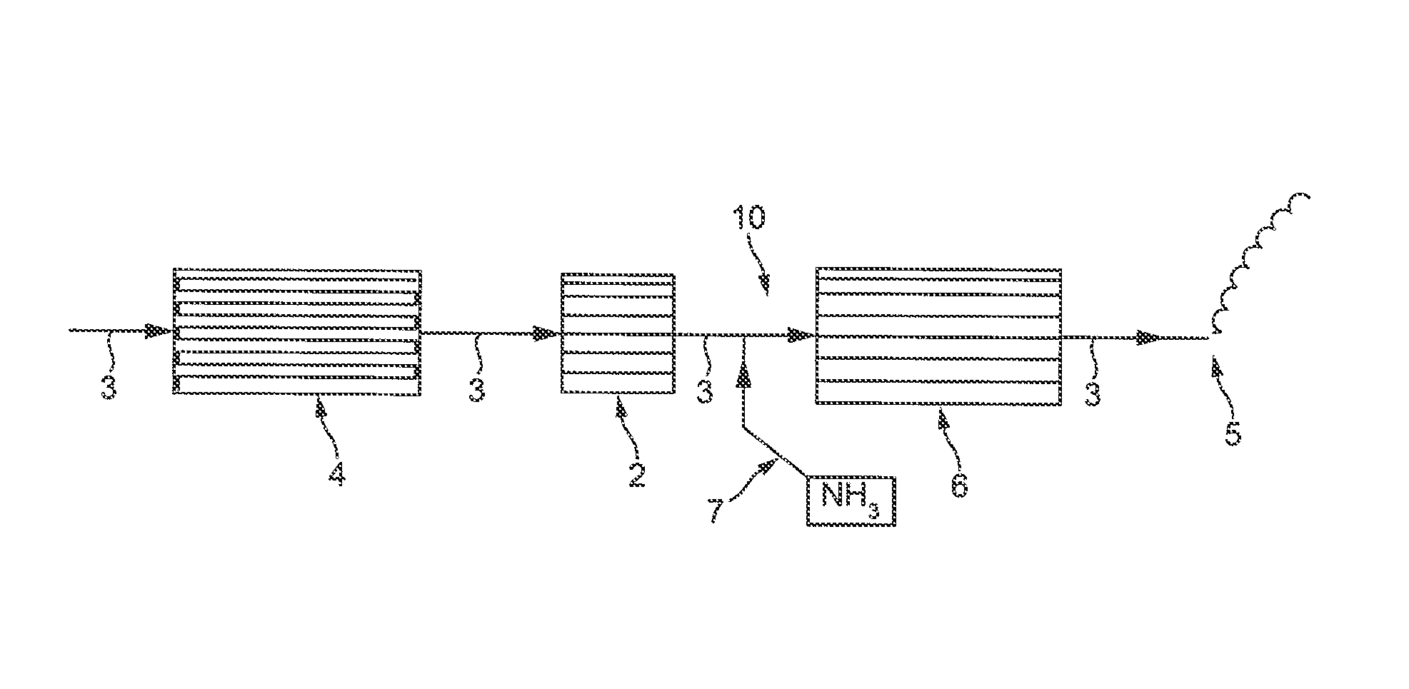
An exhaust system 10 for a vehicular lean-burn internal combustion engine comprises:(a) a first substrate monolith 6 comprising a SCR catalyst;(b) at least one second substrate monolith 4 comprising a catalytic washcoat coating comprising at least one platinum group metal (PGM) disposed upstream of the first substrate monolith; and(c) a third substrate monolith 2 disposed between the first substrate monolith and the or each second substrate monolith,wherein at least one PGM on the or each second substrate monolith 4 is liable to volatilise when the or each second substrate monolith 4 is exposed to relatively extreme conditions including relatively high temperatures, and wherein the third substrate monolith 2 comprises a washcoat coating comprising at least one metal oxide for trapping volatilised PGM.

Description

CROSS REFERENCE TO RELATED APPLICATIONS[0001]This application claims priority benefit to U.S. Provisional Patent Application No. 61 / 569,530 filed on Dec. 12, 2011, and Great Britain Patent Application No. 1200781.1 filed on Jan. 18, 2012, both of which are incorporated herein by reference.FIELD OF THE INVENTION[0002]The present invention relates to an exhaust system for a vehicular lean-burn internal combustion engine, which system comprising a first substrate monolith comprising a SCR catalyst and at least one second substrate monolith comprising at least one platinum group metal (PGM) disposed upstream of the first substrate monolith.BACKGROUND TO THE INVENTION[0003]Generally, there are four classes of pollutant that are legislated against by inter-governmental organisations throughout the world: carbon monoxide (CO), unburned hydrocarbons (HC), oxides of nitrogen (NOx) and particulate matter (PM).[0004]As emissions standards for permissible emission of such pollutants in exhaust ...

Claims


Application Information

Patent Timeline
Patent Type & Authority Patents(United States)
IPC IPC(8): F01N3/24B01J23/40B01D53/94F01N3/10F01N3/28
CPCF01N3/2066F01N3/035F01N2490/20B01D2255/407F01N2570/00F01N2510/06B01D53/9477B01D53/9495B01D2255/1021F01N13/02F01N3/0842B01D53/9481B01D2255/20715Y02T10/24B01D53/9418F01N3/0828B01D2255/1023B01D53/944F01N3/103B01D2255/2092B01D2258/012Y10S502/516Y10S502/521F01N3/021F01N3/106F01N3/20B01D2255/102B01D2258/01F01N2250/02F01N2610/02Y02A50/20Y02T10/12F01N3/0807F01N3/0222F01N13/009
Inventor BLAKEMAN, PHILIP GERALDCHATTERJEE, SOUGATOCHIFFEY, ANDREW FRANCISGAST, JANEPHILLIPS, PAUL RICHARDRAJARAM, RAJ RAOWALKER, ANDREW PETER
Owner JOHNSON MATTHEY PLC
Learn More