Oxycombustion in transport oxy-combustor

a technology of oxycombustion and combustion chamber, which is applied in the direction of fluidised bed combustion apparatus, combustion type, lighting and heating apparatus, etc., can solve the undesirable presence of oxygen in the cosub>2 /sub>stream flue gas, reduce operating reliability, and achieve low molar ratio, reduce operating costs, and effectively remove approximately 100% of sulfur oxides

Active Publication Date: 2014-04-08
THE SOUTHERN CO
View PDF18 Cites 3 Cited by
  • Summary
  • Abstract
  • Description
  • Claims
  • Application Information

AI Technical Summary

Benefits of technology

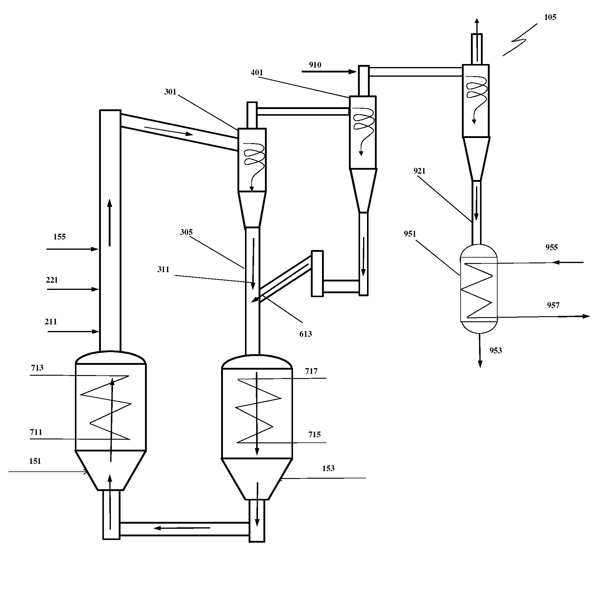
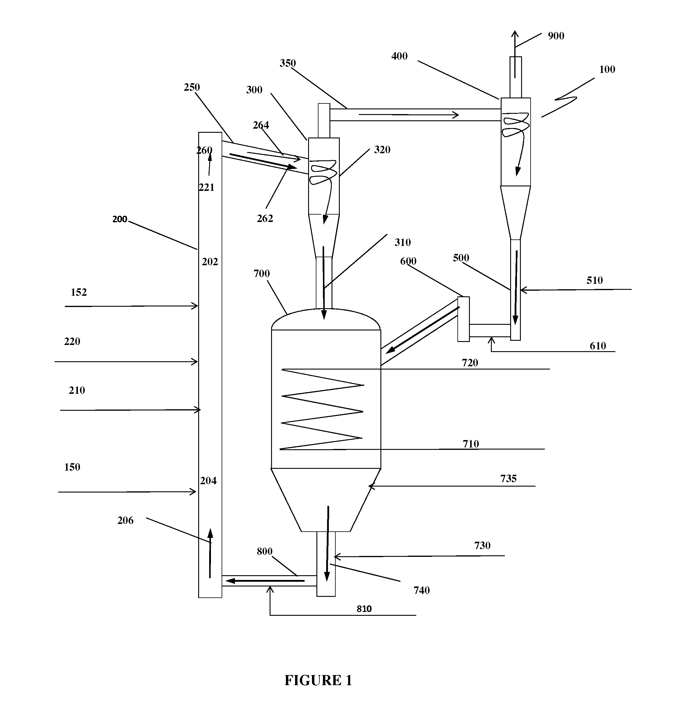
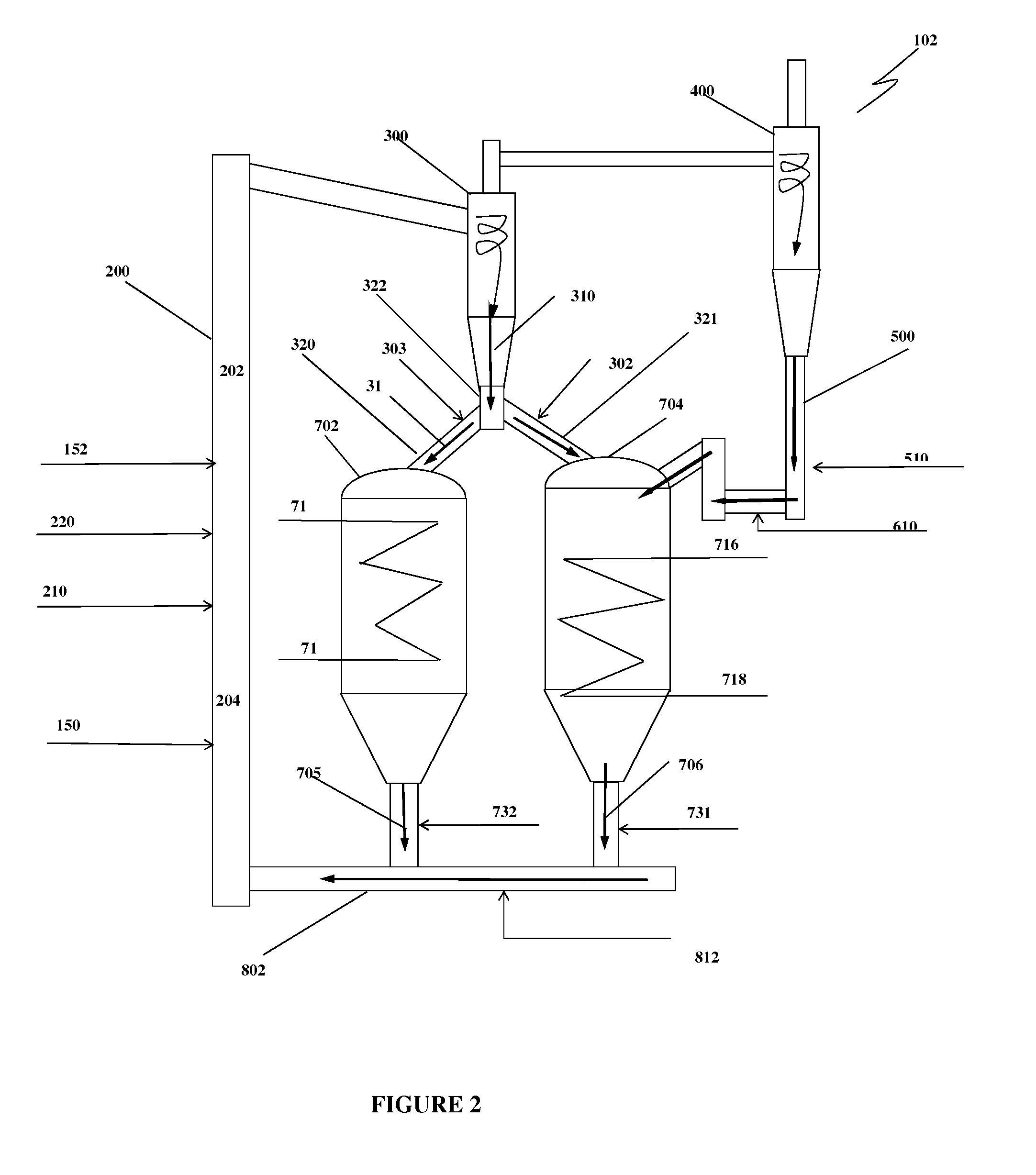
[0021]A solids stream from the solids cooler to a lower section of the riser is mixed with oxygen from the primary oxygen feed to fully disperse the oxygen by circulating solids across the cross-section of the riser. In an exemplary embodiment, the mass flow rate of the solids in the circulating solids stream is in the range of approximately 150 to 400 times the solids fuel stream feed rate to the riser. As the combustion will be substantially complete in the various elements of the present invention, the carbon content in the circulating solids is nearly zero, and the mixing process in the lower section of the riser has a low solids temperature rise. The method of achieving substantially complete combustion and zero carbon in the circulating solids is through a combination of riser design and fuel grind size. The height of the riser is designed for sufficient residence time such that the fuel with the lowest reactivity will be fully converted. The grind size of the solids fuel stream is set to a sufficiently small size depending upon fuel characteristics to facilitate higher carbon conversion by providing high solids surface area.
[0044]According to another preferred embodiment of the present invention, the solids circulation rate to the carbonaceous solids fuel mass ratio is in the range of approximately 150 to 400, to limit if not avoid any possibility of hot spots when substantially pure oxygen is used for combustion. The high solids circulation rate also makes it possible for high steam production rates and high solids carbonaceous fuel throughput in the combustor.

Problems solved by technology

Although the Anderson et al. type of process has substantial advantages compared to air-blown combustion when CO2 capture from the flue gas is required, the large amount of flue gas recycled results in high energy consumption and reduces operating reliability.
Yet, the presence of oxygen in the CO2 stream flue gas is undesirable for CO2 sequestration or for other utilizations.
The mixture of CO2 and oxygen is also more corrosive in the presence of even small amounts of moisture.
In addition, oxygen production is one of the most expensive steps in the combustion process, and discharging the flue gas with such precious oxygen is thus highly undesirable.
The aeration in the fluidized bed heat exchanger can have a negative impact on the cyclone performance and the overall solids circulation rates.
Oxy-fuel combustion in a CFB also suffers some common disadvantages of the air-fuel combustion process.
Yet, capital and operating costs increase due to the addition of the FGD into the process.
As described above, with the oxy-combustion CFB process, such large recycling of CO2 or flue gas to control combustion temperature leads to lower plant efficiencies and operational reliability.
Unlike CFB combustors, in-situ sulfur removal is not feasible with PC boiler.
Also, the fuel grinding costs are significantly higher with combustion in PC boilers as it requires much finer fuel for substantially complete combustion of feed coal.

Method used


Image

  • Oxycombustion in transport oxy-combustor
  • Oxycombustion in transport oxy-combustor
  • Oxycombustion in transport oxy-combustor

Examples


Embodiment Construction

[0054]To facilitate an understanding of the principles and features of the various embodiments of the invention, various illustrative embodiments are explained below. Although exemplary embodiments of the invention are explained in detail, it is to be understood that other embodiments are contemplated. Accordingly, it is not intended that the invention is limited in its scope to the details of construction and arrangement of components set forth in the following description or illustrated in the drawings. The invention is capable of other embodiments and of being practiced or carried out in various ways. Also, in describing the exemplary embodiments, specific terminology will be resorted to for the sake of clarity.

[0055]It must also be noted that, as used in the specification and the appended claims, the singular forms “a,”“an” and “the” include plural references unless the context clearly dictates otherwise. For example, reference to a component is intended also to include composit...


PUM


Abstract

A pressurized transport oxy-combustor with different configurations is disclosed. Substantially pure oxygen is fed to the transport oxy-combustor under pressure to combust fossil fuels, generating steam for power generation. The end product is the flue gas containing substantially pure CO2 after moisture condensation. The low excess oxygen necessary to achieve complete combustion in the combustor is scavenged by adding another fuel so that substantially all oxygen fed to the combustor is completely consumed. The capability to operate the transport oxy-combustor as a circulating fluidized bed combustor at very high solids circulation rates makes it unnecessary to use recycled CO2 or flue gas as a means to moderate and control the combustion temperature. The temperature in the combustor is effectively controlled by relatively cooler circulating solids that enter the combustion zone. A small amount of CO2 is recycled for aeration and to convey solids fuel to the combustor.

Description

CROSS-REFERENCE TO RELATED APPLICATIONS[0001]This application claims the benefit of U.S. Provisional Application No. 61 / 482,498 filed 4 May 2011, the entire contents and substance of which are hereby incorporated by reference.STATEMENT REGARDING FEDERALLY SPONSORED RESEARCH OR DEVELOPMENT[0002]This invention was made with some Government support under Cooperative Agreement Number DE-NT0000749 awarded by the United States Department of Energy. The Government has certain rights in this invention.BACKGROUND OF THE INVENTION[0003]1. Field of the Invention[0004]This invention relates generally to coal-fired electricity generating plant design, and more particularly to a transport oxy-combustor. The transport oxy-combustor is used for the combustion of coal with oxygen as oxidant to generate a substantially pure CO2 stream after condensing moisture out of the flue gas.[0005]2. Description of Related Art[0006]Oxy-combustion is part of coal-fired electricity generating plant design that has...

Claims


Application Information

Patent Timeline
Patent Type & Authority Patents(United States)
IPC IPC(8): F23G5/00F23J11/00F23C10/00
CPCB01J2208/00141B01J8/388F22B1/22F22B35/002F23C2206/103Y02E20/344B01J8/0055F23C2900/10006F23C10/10Y02E20/34
Inventor VIMALCHAND, PANNALALLIU, GUOHAIPENG, WANWANG
Owner THE SOUTHERN CO
Why Eureka
Try Eureka